About this 3D model
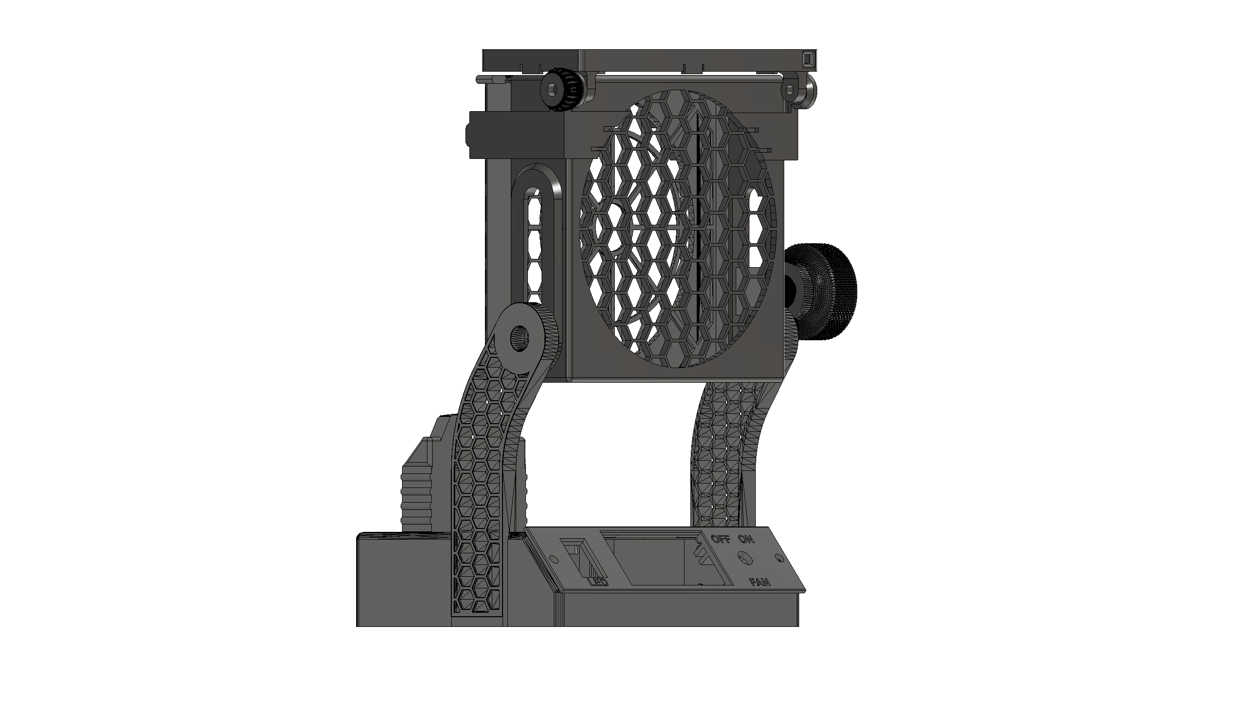
A remix of the model https://www.printables.com/es/model/84614-heavy-duty-battery-powered-solder-fume-extractor by user Lewosh. All thanks to him. All parts have been redesigned to fit the new design. What's new? - Added the possibility to use Parkside x20 batteries. It can also be used connected to a 12v dc adapter. By mounting the dc adapter that I attach in the list of required parts, you can use adapters up to 40v. ¡¡¡ Do not use power supply and battery simultaneously!!!. -The fan housing is now telescopic. -Base and cover have been redesigned to add the new electronic components. Power cut-off switch has been added. -Control panel redesigned to add a led switch and battery status monitor. -Added a led light bracket. .3mf files now have the proper print profile, such as ideal part position, layer height, fill and manual supports. You have two models to choose from, with and without battery. Both have DC connector. Print the one you think you need. *** Notice for your safety.*** Do not use the external power supply and battery simultaneously. Only use one at a time !!!. Necessary parts: Electronics: Battery status monitor x1 (Only if you are printing the battery version) Potentiometer for fan x1 DC power jack female x1 Switch x2 LED strip dc-dc converter x1 (This element is not necessary if you are going to use a 12v power supply in the model without battery.) 120mm computer fan x1 Wire Otros: Brass inserts m3 and m4 x4 Screw m3 and m4 x4 Flange Soldering iron spade male terminal x2 ( Only if you are printing the battery version ) Glue Multimeter (To adjust the dc-dc converter to 12v) TUTORIAL 1º Print the models. 2º Once printed make sure that the screw holes and wires are clean. 3º Pass each one of the cables through the hole of the battery connector and solder the terminals to them. Insert the terminals to the bottom and glue them with glue to prevent them from moving. 4º Solder the positive cable of the battery connector to the positive pole of the dc-dc converter. 5º Screw the dc-dc converter to the base with m3x8mm screws. 6º Solder a wire to the negative pole of the dc-dc converter. 7º Now it is time to adjust the output of the dc-dc adapter to 12v using the multimeter. I attach a diagram and sample images to make the rest of the connections. Reminder If you have not set the dc-dc converter to 12v, now is the time to use the multimeter. If you like my designs give me like and share. If you like them a lot invite me to a coffee. https://www.buymeacoffee.com/kjbturok https://www.paypal.com/paypalme/ChinadlaConchinchina