About this 3D model
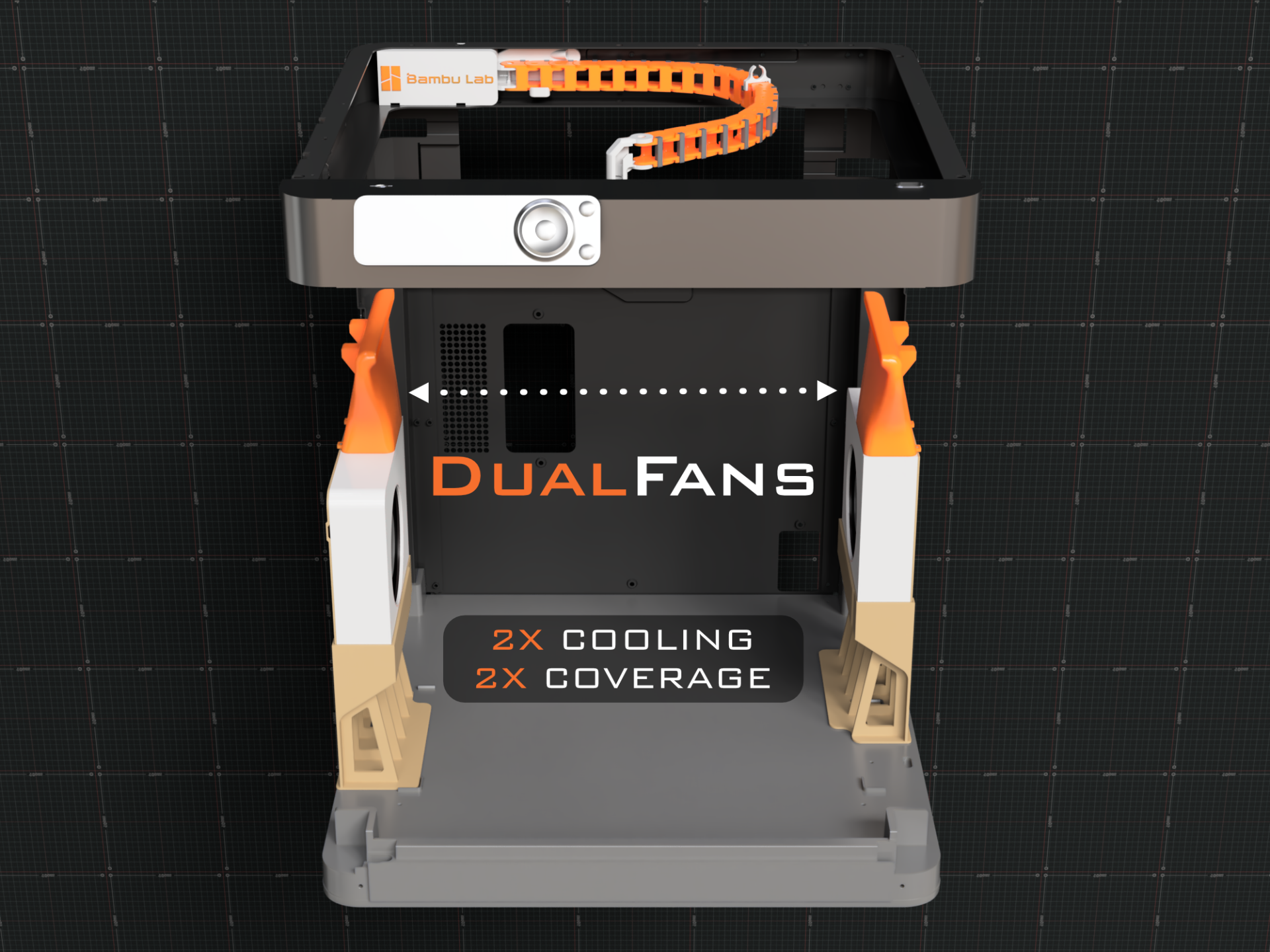
Bambu Lab P1 / X1 Series Dual Aux Fan (4/10/2023) Designed a second aux fan for Bambu Lab printers. I have another modular version of this that also uses an optional bentobox for those printing enclosed https://makerworld.com/en/models/23658 . Big thanks to @Spezo_501511 for helping with X1 / X1C testing. Contents Updates Files Additional Parts Printing Information Assembly Wiring Options The X1 and P1 Version are different! This is to account for the Lidar clearance. This will only fit on the right side of the printer! You cannot mirror to work on the left, where the original fan goes, as the frame rails are are different heights ( among other things). Update 7/28/23 Finished the design for the upgraded fan ducts that provide airflow to the back, middle, and front of the build plate https://makerworld.com/en/models/23661 Model only works with the modular version https://makerworld.com/en/models/23658 Update 7/25/23 Added multiple wiring instructions. Using fan_1 port to power the aux. Control via Bambu Studios Using fan_1 port to power the aux. Control via Gcode. Keeping the fan_1 port open for the chamber temp fan, wiring 2nd aux to the 1st aux fan. Control via normal way. Files Main Files P1 Fan Top 1A Fan Casing 2A Fan Back Plate 3A Fan Stand 4A X1 Fan Top 5A Print File P1 Print File X1 Print File Additional Parts Aux fan https://us.store.bambulab.com/products/auxiliary-part-cooling-fan-x1-series-and-p1p Qty 2 : M3*6 Print Orientation Print Settings DO NOT USE PLA, IT WILL BREAK. Please use PETG, ASA, PLA+ , etc. I used Polylite Pro PLA+ Set your K calibration and adjust setting based on your filament Quality Please see build plate file. Support Please see build plate file. Other Bed adhesion - use brim if you're having adhesion issues, its already configured in the print file so please go over the settings first. * To remove the support from the fan top , I just used pliers and pulled the support out which was pretty easy. Sometimes some of the support stuck but it was easy to clean up with a small knife. The supports on the 2 larger tabs on the fan casing should looked at after the supports are removed, just make sure it's clean on the bottom side since these tabs are what hold it tight against the fan stand. Lastly, be careful when removing the supports on the front of the fan casing, loosen and remove the main vertical support then it's easier to remove the supports around the 4 rectangular tabs. Assembly Remove the fan from casing, remove the sticker over the wiring and redirect the wiring as shown below. Don't put the fan in the printed case yet. Attached the fan top to the casing, make sure are for tabs are locked in and the front left and back walls are flush between the top and case. Place the fan into the new casing, make sure the fan is centered by using the alignment poles Attach the back plate using re-using the 3 screws that originally held the fan into the casing. Slide the back plate on up/left, making sure to keep the wiring in the channel and then slotting the top two little tabs on the back plate into the spots on the back of the fan top. Tighten the screws 90% of the way making sure the backplate can still move a little. Slide the upper assembly onto the fan stand, same way as the OEM aux fan and use the 2 longer screws that come with the aux fan to tighten the case against the stand. Then make sure the back plate is squared up and tighten the 3 screws the remainder of the way. MOVE THE BUILD PLATE ALL THE WAY DOWN FOR THE NEXT STEPS The stand connects to the floor via lining up the L shape cutout with the L shape extrusion on the floor. There is also a caution sticker and under that sticker is a hole that we will use to screw the stand to the floor. I re-used 1 of the 2 shorter screws that came with the aux fan. Next tilt the fan into place. The re protrusions on the fan top should “almost” line up with the 2 holes in the frame. They are offset a little. Then use 2 M3*6 screws to hold it in place. Wiring Options (Option 3 is the best and requires no modification to existing aux fan wires) Option 1- Using the fan_1 port ( where the chamber fan would connect) and Bambu Studios to control the fan. Follow the instructions to remove the back plate to plug in the aux fan. The fan plugs into Fan 1 while the original aux fan is plugged into Fan2 Cable manage the wiring Bambu Studio So I know you can change the Gcode to make it work with the fan which is “M106 P3 S0 ; turn off chamber fan” (option 2 below) but you can also change the config to make it show up in Bambu Studio. For me on PC it's under C:\Program Files\Bambu Studio\resources . Open the Config file with an application like Notepad++ https://notepad-plus-plus.org/downloads/v8.5.1/ Under "FUNC_CHAMBER_FAN" : false," change it to true ""FUNC_CHAMBER_FAN" : true," . Notepadd++ will ask to change this under administrator, click yes and save the file. { "printers": [ { "display_name": "Bambu Lab P1P", "func": { "FUNC_CHAMBER_TEMP": tr