About this 3D model
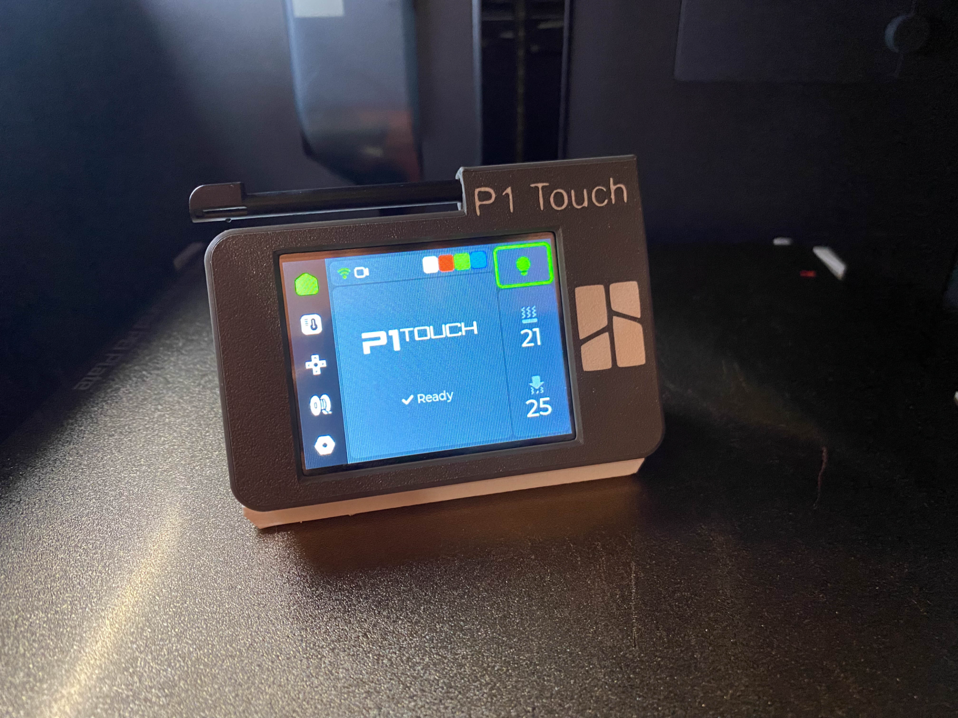
Version What was added Date Version 1.0 Main Body and Desktop stand 1.10.2023 Version 1.1a Added Top face with pen holder on the opposite side 1.10.2023 Version 1.1b Added more space for SD card due to migration to XTouch Added modified Top plate with XTouch logo 3.10.2023 Version 1.5 Soon - with the Printer Base TBA Hi! This is P1 Touch Portable version. It's small and portable! It uses magnetic pogo pin and neodymium magnets for charging and connecting to the printer base*. How to assembly: Take Magnetic Pogo pin with flat end and solder 2 wires (use shrink tubes) Take other one Magnetic PogoPin and solder +5V and GND to the terminals (use shrink tubes) Take 20mm x5mm magnets and put them inside the main body (put them with fixed polarity) Insert Magnetic Pogo pin with 2 wires and put it inside body (you can use a little screwdriver to push it down) Take USB C charger and solder 2 wires from pogopin inside body to the + and - on the charger (solder them to the charging pads) - Remember about correct polarity). At this point you can check all connection, connect USB to the computer port (5V) and connect PogoPins halves with itself together and blue led should light up on the charger Take RockerSwitch and solder 2 wires - after that insert switch to the body on the right side Take StepUp 5V Converter and to the Vin pad solder one end of the RockerSwitch wire and second wire from the RockerSwitch connect with + OUT on the USB C charger Take wire and solder - OUT from the USB C Charger to the GND on the StepUp Converter (solder that wire to the next GND near Vin on the converter) Take out cable from the ESP32 module and take out 2 inner wires from that cable. You should keep one black and one red wire. Solder that wires to the converter. Red one ( +5V ) to the Vout and black one ( GND ) to the GND (solder that wire to the next GND near Vout on the converter) Right now be carefull and patient. Take out LiPo battery and connect + and - terminals to the B+ and B- on the USB C charger. LiPo are dangerous if they are punctured, overheated, bended, etc… so be carefull After that connect wire with JST connector to the ESP32 module and check if it's turning on Now take some double sided tape and tape down battery, converter and usb c charger to the body You can use HotGlue and glue the wires from the pogopin inside body After that screw down the ESP32 module to the frame and cover it by pushing down the Top face Congrats! Right now you are assembled the main body! You are awesome! After that print the Desktop Body and put the USB cable with PogoPin inside (remember about correct polarity). It should last about 1h witout charging cos the screen is turning off after some time. *Printer Base is included but it's a ‘demo’ version of it. I'm trying to make something better than that. It's working right but i'm not happy with that :) I will update that files soon. Feel free to comment! And a little bonus. REPRINTS :D