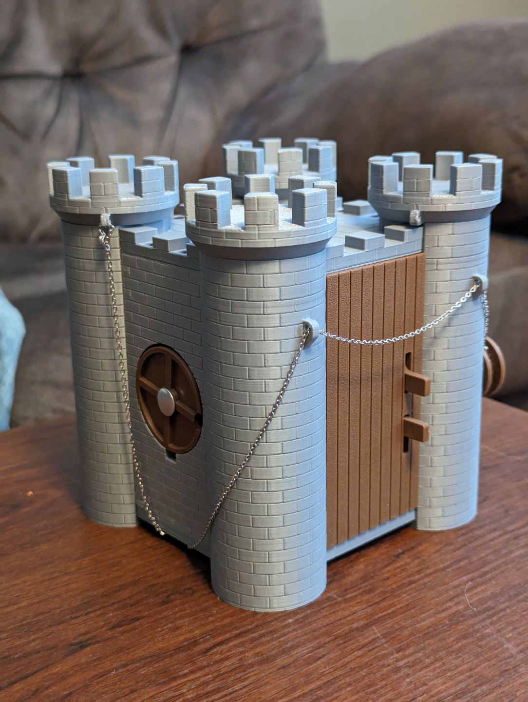
About this 3D model
V1.3 (Dec 21, 2023) Included QR code plaques for accessing the videos for the solution to the puzzle as well as how to reset it. They are included in the new V1.3 file on the last plate. If you want these QR plaques, please download the latest file V1.2 Update (Dec 17, 2023) Removed QR rick-roll code from the standard 3MF file. The youtube account was apparently closed so I am just going to pull it from the design. I apologize for anyone who has printed the bottom piece to date, you will need to re-print plate #3 of the design Added Videos for solution and how to reset V1.1 Update Included a tweezer into the build so that you do not have to purchase your own to include Change 1 dimension by 0.5mm on the deadbolt, not a big deal, just a very very small amount of additional clearance in one direction when printing with a silk filament which is a nice to have Decided to change the jewelry chain routing to only include 1 rear pillar. After many play testings, only including 1 pillar as the restriction felt like the right move. It draws peoples focus to that pillar and it is easier to get an accurate length on the chain. See last image below Decided to copy/paste the instructions here so people know what they are getting into This is a long term passion project of mine, creating puzzle boxes for D&D Adventures. This one is castle themed, and is a mechanically heavy solution. It includes hidden mazes, springs, magnets, and discovery by tear down. It also includes a few red herrings to throw people off. Video for Solution: Video for Resetting: Puzzle Box Manual V1.1 By: Mechengg Planning Filament Requirements Type Color Model (g) Flushed (g) Total (g) PLA (+) Grey 596.49 0.02 596.51 Accent* 130.23 0.01 130.23 White 3.72 0.37 4.09 Black 0.49 0.35 0.84 731.67 Hardware Required Brass Nut Insert M3 x 6mm x21 M5 x 6mm x2 Hex Bolt w/ Washer M3 x 8mm x20 M5 x 12mm x1 Threaded Rod M3 x 60mm x1 Spring 7.5mmD x 11mmL x2 7.5mmD x 19mmL x3 9.5mmD x 19mmL x2 Washer ¼” Standard x2 Binding Post ¼”D x ¾”L x1 Magnets 15mmD x 3mmL x16 Jewelry Chain 1mm link width 36” Tools Required Soldering Iron Allen keys CA Glue Loctite (or use CA Glue in place) Print Settings Quality Layer Height: 0.12mm First Layer Height: 0.20mm Ironing: All Top Surfaces Print Order: Inner/Outer/Infill Strength Wall Loops: 3 Top Shell Layers: 5 Bottom Shell Layers: 5 Sparse Infill Density: 15% Sparse Infill Pattern: Gyroid Speed All Standard Settings Support Enabled: Yes Type: Normal (Auto) Others Brim Type: Auto Prime Tower: Enabled Print Time 1D 12H 35m Print Orientation & Parts List 1 Bottom 2 Gatewheel 3 Pillars – Left Combined 4 Pillars – Right Combined 5 Shield 2 6 Side – Door – Box Rear 7 Side – Door – Deadbolt 8 Side – Door – Inside Box 9 Side – Door – Pin Lower 10 Side – Door – Pin Upper 11 Side – Door 12 Side – Maze 13 Side – Rear – Cover 14 Side – Rear – Slide Lock Head 2 15 Side – Rear – Slide Lock Pin 16 Side – Rear 17 Side – Shield 18 Top 19 Tower – Common Top Cap 20 Tower – Magnet High 21 Tower – Magnet Low 22 Tower – Magnet Plug 23 Tower – Maze 1 24 Tower – Maze 2 25 Tower – Maze 3 26 Tower – Tweezers Not shown – Tweezers are now included on build plate 4 Assembly Soldering Nut Inserts Using soldering iron, inset brass nut inserts into the “Side – Door” until flush (M3x6mm x2) Using soldering iron, inset brass nut inserts into the “Side – Door – Inside Box” until flush (M3x6mm x2) Using soldering iron, inset brass nut inserts into the top and bottom of the “Side – Maze” panel until flush (M3x6mm x4) Using soldering iron, inset brass nut inserts into the “Side - Rear” top, bottom and interior face until flush (M3x6mm x8) Using soldering iron, inset brass nut inserts into the top and bottom of the “Side - Shield” panel until flush (M3x6mm x4) Using soldering iron, inset brass nut inserts into the bottom of “Tower – Maze 2” until flush (M3x6mm x1) Using soldering iron, inset brass nut insert into the side of the “Pillars – Right Combined” assembly until flush (M5x6mm x1) ***Note larger M5 size*** Using soldering iron, inset brass nut insert into the “Gatewheel” until flush (M5x6mm x1) ***Note larger M5 size*** Assembling Bolts & Rods Using Loctite, secure the threaded rod (M3 x 60mm) into the “Tower – Maze 2” assembly Using Loctite, secure the bolt (M5 x 12mm) into the “Gatewheel” assembly from the direction shown below Assembling Shield Panel Insert “Shield” into pre-assembled “Side – Shield” assembly Using Loctite, install Binding Post (1/4” x ¾”) through the center hole, the blank pin on the outside and the slotted side on the inside of the panel. Tighten then loosen just enough to allow for the shield to turn with light resistance Assembling Rear Locking Pins Install Spring (7.5mm x 19mm) then washer (1/4”) onto the “Side – Rear – Slide Lock Pin” in the below order Using CA glue, secure the “Side – Rear – Slide Lock Head 2” into the “Side – Rear – Slide Lock Pin” assembly above, ensuring to align the flat surfaces of the pin and head parallel