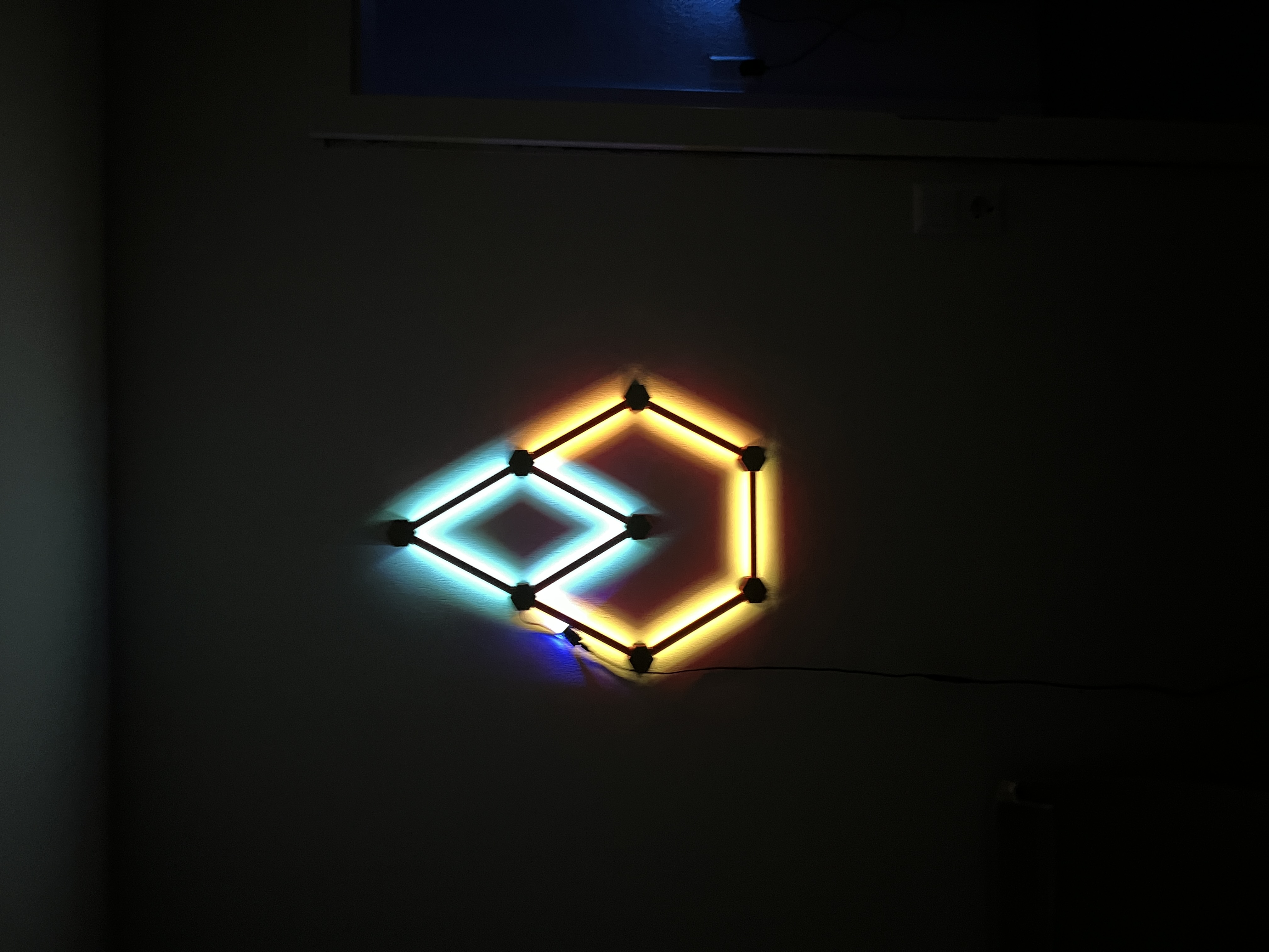
About this 3D model
This is a small WLED gadget inspired by the original Nanoleaf. It is implemented with a Wemos D1 mini and WS2812B LEDs (60/m) and can thus be realized quite cost-effectively. ATTENTION!! Currently, I am powering this via the MicroUSB of the D1 mini and have left it at 850mA in WLED . This should only be increased if you are using the 5V via the pins. UPDATE 9.1.2022 ############## The hole for the power cable has been slightly relocated again. (v4) This way, it can now be soldered directly under the Wemos to ensure the 5V power supply. UPDATE 7.1.2022 ############## The base of the WEMOS D1 mini has been changed again. I had made it about 4mm too long. The hub was also provided with a hole again for the end cap. Another hole was added so that a 5V power supply can be soldered directly to the pins. I'm leaving the MicroUSB opening in so that one might be able to flash another sketch or a new version of WLED . Fusion360 file has been added. UPDATE 3.1.2022 ############## Files for a base where the Wemos can be inserted have been added. A housing for the power connection via an external power supply is in progress. What is needed? - WEMOS D1 mini → on Amazon depending on the length of the chosen shape - WS2812b → on Amazon - Heat-set inserts M3 → on Amazon - M3x8 → on Amazon Summary: Step 1 - Devise a shape and count parts Step 2 - Print parts Step 3 - LED strip Step 4 - Soldering Step 5 - WLED Step 6 - Hang up and enjoy ######################################## -Step 1: Devise a shape and count parts At the beginning, you should consider a shape you would like to have. A few examples are provided in the pictures above; of course, there are countless more. However, it should be noted that we are using WS2812b LEDs here, which require a continuous data line, and this should always be present. Otherwise, they cannot be controlled via WLED. For a “foot”, you always need BASE, hub, and TOP. This is usually done twice for an LED strip, regardless of whether you print it for 5 or 10 LEDs. -Step 2 - Print parts Now, of course, you should print the parts in sufficient quantity, according to the pattern you devised. -Step 3 - LED strip While the parts are printing, you can start cutting the LED strips to size. This can be done in groups of 5 or 10, depending on the pattern you have chosen. If the individual LED holders are already printed, you can glue or simply click the LEDs into place. The orientation doesn't matter yet. -Step 4 - Soldering Take the soldering iron and melt the heat-set inserts into the BASE. I recommend all 3, but 1-2 would also suffice. Then arrange the hubs and LED strips according to your chosen pattern. You should pay attention to where you start and ensure that the data line is continuous and always points in the correct direction. Now, solder the 3 lines 5V, DATA, and GND with cables as thin as possible. Since there isn't much space, these cables should also be cut to length as precisely as possible. -Step 5 - WLED Now you flash WLED onto the D1 mini and can already download the WLED app for your phone. I had already made a video on how to do this for another project. The procedure is the same. Step 6 - Hang up and enjoy Once the entire construct is finished, you can attach it to the wall. To do this, leave the TOP covers off. This way, you can hold it against the wall and mark the positions through the holes with a pencil, or screw it directly into a wooden or drywall with a drywall screw. Otherwise, pre-drill and secure with an appropriate dowel and screws.