About this 3D model
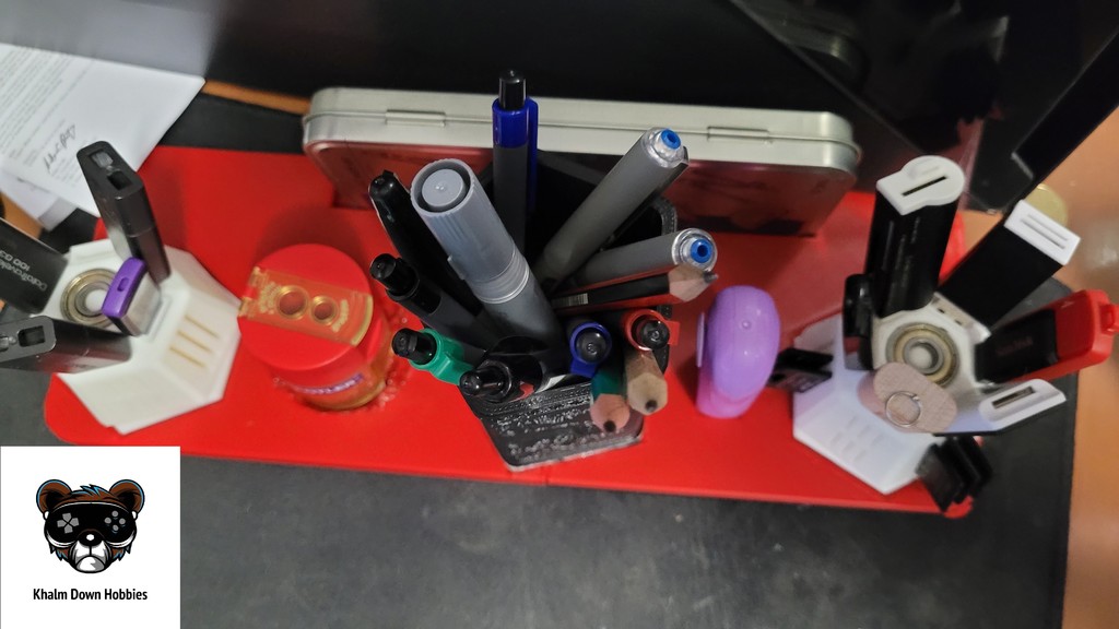
Summary This is a simple desk organiser or organizer for the Americans. It ties a few key designs together along with a spot for my pencil sharpener (The one used in the images was not the original thus the jank mod) a rubber (eraser for the Americans) and a Norris Math set which is a common instrument set here in Australia. This is cut into 2 pieces marked left and right as well as a whole if you have a large enough bed. Externally printed parts that make this up are: Pen Holder originally uploaded @ https://www.crealitycloud.com/model-detail/652e5a6206d6cf3ae6afd1b0 The Micro/SD/USB Rotating Organiser (Organizer) are from https://www.thingiverse.com/thing:4874570 by Texas_In_FPV with a massive shout out for a favourite design of mine and one of the first things I printed that needed bearings. These need 2x 608zz each to rotate. (Side note my wife and I constantly refer to these as the USB Darlek’s from Doctor Who. To glue the 2 halves together in my case as I’ve printed V1.0 I had a soldering iron to make some clearance, so I just did a plastic weld. Otherwise, I would use superglue or another preferred glue option. Printed easily in imported orientation and I’ve done mine in a part roll of PLA and a bit more of another roll in PLA. Printed on the Creality K1 Normal Profile at 3x3 at 10% infill. Revisions: V1.0 – Initial Sketch, design and prototype completed, printed as 2 halves, and found some clearances were insufficient. V1.1 – Added 0.4mm onto 2 of the tight clearances with good results & remodelled the sharpener position around the sharpener I've used. Print Settings Printer Brand: Creality Printer: K1 Rafts: Doesn't Matter Supports: No Resolution: 0.2 Infill: 10% Filament: Esun PLA+ Black & Fire Engine Red Notes: Printed in all default Hyper PLA profile on the K1, had some minor extrusion issues due to me making an error and the old extruder being a bit temperamental. Came out more than good enough for my purposes so didn't reprint. Post-Printing Processing steps Glue left and right together, in my case I used a soldering iron and just plastic welded the 2 sides together as it was convenient for me at the time. Alternatively you could use the cut and pin tool in Prusaslicer to get a nice clip response. How I Designed This Design Process The design for this followed the usual measure all, add 0.4mm for fit and sketch. Sketch also included a 12mm fillet on the corners as sharp corners generally slow down a print. After sketching I've extruded the deep bases and the upper bases at different times to allow for the effect in heights I wanted. Outer walls allowed for at 2.8mm from recesses for parts. A 1-2.5mm chamfer pending the location was used on recesses and on the bottom to make for easier removal. This was iterated on again with some changes following initial print, this is for others benefit as I considered this a 1 day design, print and use project.