About this 3D model
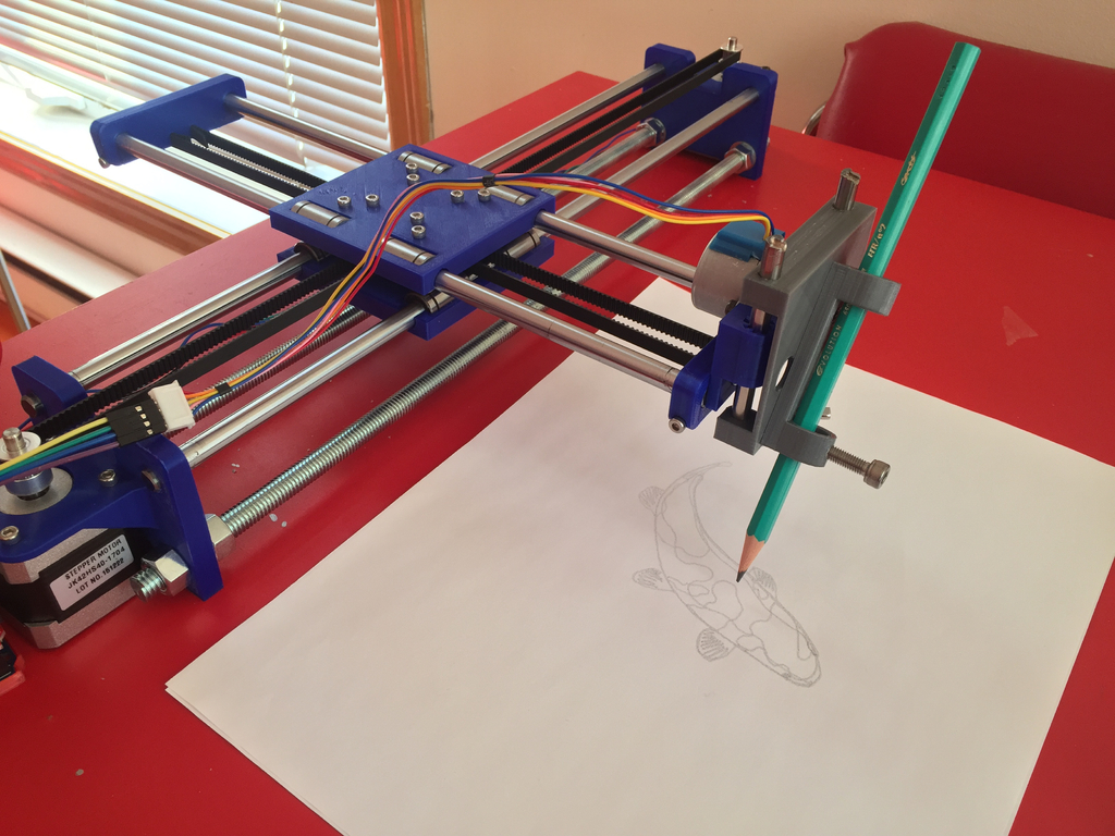
Boost Me Summary My take on Misan's drawing machine. I made one with a grbl controller and a CNC shield and adapted Misan's parts to be 3D printed. Please read Misan's instructions as well. The drawing machine is a small three axis robot that controls a pen or any drawing implement over a canvas. It is a complete open source design and aims to teach the basics of robotics. Budget for one is about 80$. You will need a 3D printer. The Z stage does not use a servo, as in Misan's machine, but rather one of those cheap 28BYJ stepper motors you can find for 1.50$ on eBay. NOTE: The photos are of the current prototype, some of the modifications to the various bits and pieces have not yet been tested. If you have a question, first search in the Comments section. If you can't find an answer, then ask in a Comment. I will answer as fast and as much as I can. Please, share your makes! Print Settings Supports: Auto, on build plate, critical regions only. Resolution: 0.2 mm Infill: 15% minimum Filament: Your favourite filament brand PLA Notes: The Y end stops take a lot of tension from the belt. Making them as strong as possible to prevent flexing is not a bad idea. You may want to increase perimeters. How I Designed This This thing was made with Tinkercad. Get it here . How-to Grocery list Definitely not 550US$ worth of parts ... Below are some searches on eBay that you could use for your own machine. I am not affiliated with any of the vendors that those searches may yield. Please proceed with caution on eBay. You will need: 1 x Arduino (any cheap clone will do) with USB cable 1 x CNC shield . Look for the ones with included jumpers. It's a drag when you don't have them and you need to configure microstepping. 3 x Stepper drivers 1 x 12V power supply (the one I have is a quite beefy 12.5A, salvaged from another project) 4 x 8 mm diameter rods , any length you want (by pairs though). I used 2 x 400mm for X and 2 x 300 mm for Y (recycled from printers and scanners.) With these lengths, and the new Z stage, I get about 312(X) x 212(Y) x 23(Z) mm of workspace. 2 x X lengths of 10 mm (or 3/8") threaded rod, with associated bolts, washers and nuts 8 x LM8UU linear bearings 2 x NEMA 17 steppers Cables and connectors 5 x smooth idler pulleys (16 teeth or 10 mm, 3 mm bore) 2 x pulleys (16 teeth, 5 mm bore) (you can also use 20 teeth with different grbl settings) GT2 belt : to know how much you need, add your X to your Y, multiply by two and add two inches for luck An assortment of M3 bolts in various length and their nuts For the Z stage: 1 x 28BYJ-48 stepper motor (12V) 1 x M5 bolt to secure the pen to the Z carriage 2 x 60+ mm of 6 mm diameter rod (I got mine from an old scanner) Model Files If you experience difficulties with the OBJ format, go to TinkerCad here , copy the project to your account and export to STL. Assembly Before installing the stepper drivers on the CNC shield, install jumpers for microstepping . I installed all three jumpers on the three axis. Such precision may not be necessary for the Z axis, unless it's holding a brush and you want to control the strokes. You may have to open the stepper to cut a trace on its PCB to disconnect the red wire (see here ) and use: orange, pink, blue, yellow, in that order (blue, yellow, orange, pink should work too) Adjust the potentiometer on A4988 counter-clockwise until the motor runs but does not overheat ( check this article for details ). The last model file and photograph show (hopefully) how it all fits together. grbl You will need to re- compile grbl to activate CoreXY control. Before you compile, change config.h as such: #define HOMING_CYCLE_0 (1< #define HOMING_CYCLE_1 (1< // and this below goes uncommented #define COREXY Control Software For control, I am using CNCjs . Neat package. I use Inkscape with Gcodetools extension to generate gcode. YMMV. grbl Settings (YMMV) $4=0 (step enable invert, bool) $5=0 (limit pins invert, bool) $6=0 (probe pin invert, bool) $10=3 (status report mask:00000011) $11=0.010 (junction deviation, mm) $12=0.002 (arc tolerance, mm) $13=0 (report inches, bool) $20=0 (soft limits, bool) $21=1 (hard limits, bool) $22=0 (homing cycle, bool) $23=0 (homing dir invert mask:00000000) $24=25.000 (homing feed, mm/min) $25=500.000 (homing seek, mm/min) $26=250 (homing debounce, msec) $27=1.000 (homing pull-off, mm) $100=96.000 (x, step/mm) or 80.000 if you used 20 teeth pulleys $101=96.000 (y, step/mm) or 80.000 if you used 20 teeth pulleys $102=814.000 (z, step/mm) $110=20000.000 (x max rate, mm/min) $111=20000.000 (y max rate, mm/min) $112=2200.000 (z max rate, mm/min) $120=200.000 (x accel, mm/sec^2) $121=50.000 (y accel, mm/sec^2) $122=200.000 (z accel, mm/sec^2) $130=212.000 (x max travel, mm) $131=312.000 (y max travel, mm) $132=23.000 (z max travel, mm) Extensions and Derivatives For stronger Y axis ends, see Drawing Machine - thicker walls for rod fix screws by FiX2k. For cable management see Simple tube system for the Drawing machine b