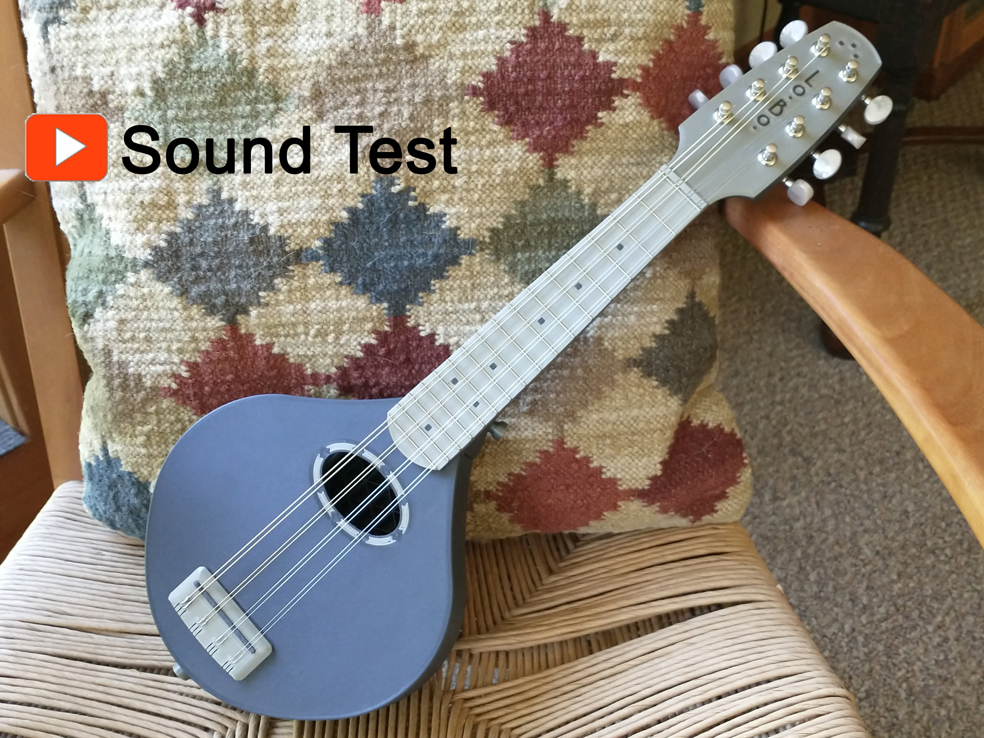
About this 3D model
*** Updated version with additional bracing for stability *** I had good success with my steel string guitar , but it required a huge printer. For folks wanting a more manageably sized project, I decided to try a mandolin instead. The main issue for any plastic instrument with steel strings is the tremendous string tension involved - about 150lb total (!) for this mandolin. Not only does it have to not implode when the strings are at full tension, but it also can't creep over time. In this updated version, I have added aluminum ribs to the bracing of the soundboard, and have also added aluminum stiffening ribs in the neck (essentially a fixed truss rod), all formed from 1/16" thick sheet aluminum. I've also added some internal diagonal struts inside the body to prevent body flex. The other big challenge was to create a soundboard that would fit on a a Prusa Mini+ bed (180x180mm) and still resonate well. I still wanted a full-scale mandolin (13.5"), so this meant that the bridge would need to be mounted near the end of the body. Rather than use a traditional floating bridge and tailpiece, I opted for a guitar-style bridge that excites the soundboard in a bending mode which can still provide higher amplitude vibrations when the bridge is not centered on the soundboard. The last challenge was creating a soundboard light and stiff enough to project well. I kept the top very thin (0.6mm/3 layers). But then I added triangular lattice bracing across the top to distribute the energy. The lattice bracing (shown in the next to last photo) is actually an exposed triangular infill pattern that prints more efficiently and with greater integrity than if I had modeled the ribs discretely. Additional Parts Needed 6-32 x 3/8" screws (3) for securing the bridge 8-32 - ½" screws (2) for the strap pins ¼-20 x 1.375" socket cap bolt (1) for the bolt-on neck ¼" x 0.55"OD washers (2) ¼-20 nut (1) 1/16" sheet aluminum (approx. 12" x 6") Straight fret wire, like this from Amazon Tuners, 25mm post spacing like these Strings: 10-34 light 80/20 strings, loop end (D'Addario, Martin or Ernie Ball) 2-part epoxy, 30 in. or longer set time (I used Devcon 2-ton epoxy) Filament Choice I first printed this using Sunlu Carbon Fiber PLA because when I printed my guitar many years ago, the CF PLA filament I used added significant stiffness. After printing several versions of this mandolin, though, I determined that the Sunlu CF PLA was adding no stiffness, strength, or creep stability. I ended up reprinting it using standard PLA which worked maybe even better. Still, there are some CF reinforced filaments (PLA, PETG or PC) that might provide better stiffness and creep resistance. Unfortunately, hardly any manufacturers (except for makers of hideously expensive engineering grade materials) post data on parameters such as the Young's Modulus or yield strength. (Hint, hint, Prusa.) Plain PLA is one of the stiffest non-reinforced filaments, but unfortunately, it has low thermal resistance. Therefore, you do not want to leave your mandolin in a hot car, or even sitting out in the sun on a warm day. I also recommend de-tensioning the strings if you aren't going to be playing for a while to reduce the chance of the plastic parts creeping over time. (Same as they recommend for wooden instruments.) Printing All of the parts, due to the loads on them, have pretty specific print settings (number of walls, in-fill density and pattern, etc.) so I've provided .3mf for all the parts. The back, top and headstock plate all need some special handling: Headstock Plate: This consists of the plate itself and the color-contrast inlay that is printed separately using a print-on-print technique. You first print the 2-layer thick inlay in one color, then change the filament and then start a second print job of the plate itself that prints on top of the inlay. But between the print jobs, you have to keep the motors and heaters turned on after the inlay print and also prevent homing and bed levelling before the start of the headstock print. The .3mf files I've provided have modifications to the starting and ending g-codes. Just start the inlay print and just before it ends, you'll be prompted to change filament. Then just start the plate print job. You'll notice that there is a rectangular fiducual boarder around both the inlay and the plate. This border insures that when the two parts are centered on the build plate, they will be correctly aligned with each other. For various reasons, you can't really do this any other way (that I've found) using PrusaSlicer. Back: The back is actually 2 separate parts contained in a single object the back itself, and a separate object that becomes lattice bracing. The solid part of the back has one set of printing parameters, but the bracing part gets printed with zero perimeters, zero top layers and zero bottom layers – nothing but infill (10% triangular). This infill forms a lattice bracing, but also supports the curved arch of the ba