About this 3D model
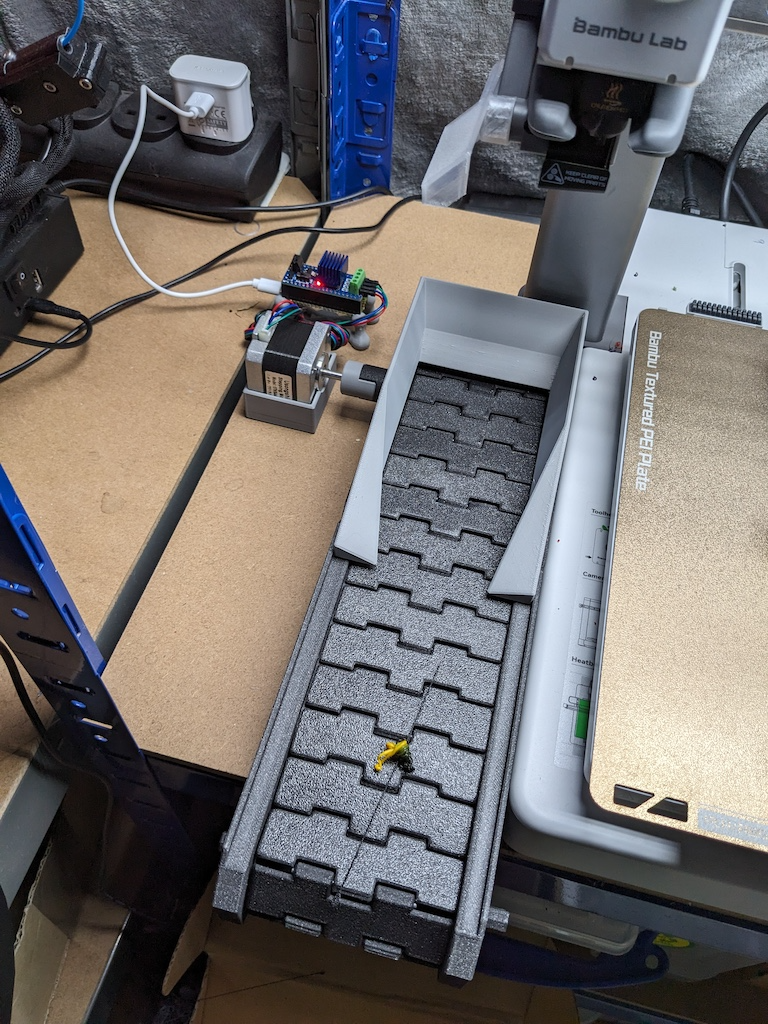
Loving my A1, but it's a little messy… and I'm a little lazy. So I developed this poop conveyor. This project is not intended to define how you power the conveyor, I use a pico-controlled 38mm high NEMA17 stepper, which is less than ideal, but works for me. If there is any interest, I'll publish how I made my electronics, and upload a blank coupler so you can customise the connection. You'll be good if your drive spindle centre is 28.2mm off the ground. Additional bits You'll need four 608 bearings, 3d printed ones will do . Ideally, you'll also have a poop deflector that aims the poop more downward, like this one . You'll need to work out a way to drive the conveyor, You may also require two M3 screws to hold the spindle caps on the one spindle. Tracks are assembled with filament from the end of a roll. Printing I'd recommend printing everything in PLA, for no particular reason, it's just easier and the project has no specific needs. The tracks work fine for me in PLA, but if you're printing in PETG a lot, then the poop can be quite hot, and I have had it stick to the conveyor a bit until it's scraped off underneath after a while. Maybe print the tracks in PETG for more heat tolerance. Assembly Slide the box halves together and insert the lock pins in the insides. Add your bearings of choice. They should be tight, but not require a hammer. Assemble the track using 32 links, don't close the loop yet. Depending on what you print them in, the holes may require drilling out to 2 mm. They are designed to use a piece of end roll filament as it is naturally curvy enough to ‘lock’ in place. Slide the track in from the ‘bin’ end, and rest it on the track support in the box. Put the drive wheel inside the box and slide a spindle through the bearings and drive shaft. Put the second drive wheel in for the ‘bin’ end but don't put the spindle on it yet, and then close the track with the final bit of filament. If you lift the box and hold it from the drive end, the track should hang at the right point for you to insert the second spindle. For the spindle at the ‘bin’ end, you can screw on the spindle caps with M3 screws of your choosing. Now you just need to attach the motor to the drive ned and you're off. Electronics I use a PICO (with headers) to power things, I have no idea how to set this up and get stuff working properly, so I followed the PICO install micropython guide and it seemed to work eventually. I also use the motor shield and a NEMA 17 stepper motor . Here is the code I used to drive it. Tweak, and you do you. I can't seem to upload a python file. ##################################### from machine import Pin import time led = Pin("LED", Pin.OUT) # Stepper motor controller M1E = 17 # Enable M1A = 21 # Phase 1 M1B = 20 # Phase 2 M2E = 16 # Enable M2A = 19 # Phase 1 M2B = 18 # Phase 2 #step_count = 8 m1e = Pin(M1E, Pin.OUT) m1a = Pin(M1A,Pin.OUT) m1b = Pin(M1B,Pin.OUT) m2e = Pin(M2E, Pin.OUT) m2a = Pin(M2A,Pin.OUT) m2b = Pin(M2B,Pin.OUT) step_ms = time.ticks_ms() # to calculate deltas step_delay=1000 step_now = -1 # Starting state led_ms = time.ticks_ms() # to calculate switch off LED time led_delay=10; def setStep(p1, p2, p3, p4): m1a(p1) m1b(p2) m2a(p3) m2b(p4) def doStep(): global step_now, step_count, n step_now += 1 if step_now >= step_count: step_now = 0 setStep(n[step_now][0], n[step_now][1], n[step_now][2], n[step_now][3]) def setup(): global n, led_state, step_count # motor loop enable, set value 0 to disable m1e(1) m2e(1) # Set up the motor driver energise loop step_count = 8 n = list(range(0, step_count)) n[0] = [0,1,0,0] n[1] = [0,1,0,1] n[2] = [0,0,0,1] n[3] = [1,0,0,1] n[4] = [1,0,0,0] n[5] = [1,0,1,0] n[6] = [0,0,1,0] n[7] = [0,1,1,0] led(0) print("Setup complete") def loop(): global step_ms, step_delay, led_ms, led_delay now_ms = time.ticks_ms() if now_ms > (step_ms + step_delay): led_ms = now_ms step_ms = now_ms led.value(1) doStep() if now_ms > (led_ms + led_delay): led.value(0) setup() while True: loop()