About this 3D model
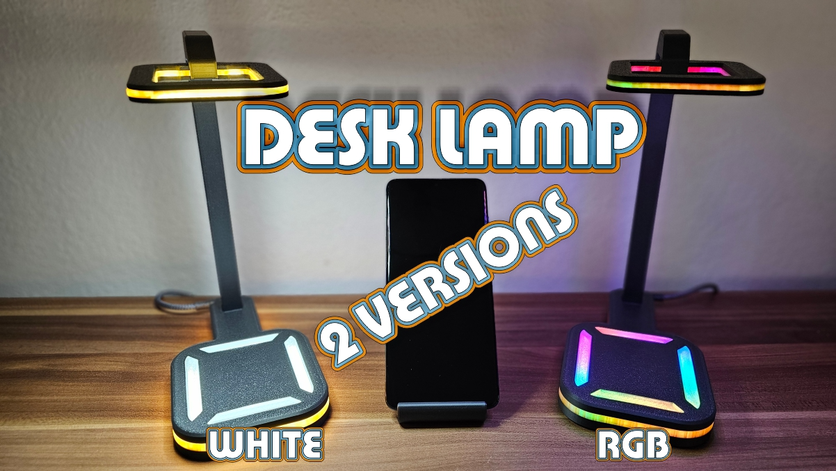
Desk Lamp + QI + ALEXA + RGB + Phone Holder Hi, I would like to introduce you to my Desk lamp with mobile phone holder and QI charging function. The project was a lot of fun because you can combine so many things. The lamp parts are ONLY plugged in, so no gluing is necessary, but it's up to you whether you want to glue the individual parts together. I made two versions of the lamp. One that only lights up white and can also be mastered by beginners in the field of electronics and a somewhat unusual version with ARGB lighting, which can of course also light up white ?. You can equip both with the QI charging function , but of course this is not a must. You can of course also use existing LED strips, just pay attention to the width. The ARGB version can be controlled via a web interface, an app on your mobile phone or via ALEXA. In order to realise this, I will also provide you with the links below. Now let's get to the things you need for this. I will also provide you with the links. Materials I have used. For the print: - Grey PETG from Bambu Lab - colour code 30102 - Translucent PETG Colourless from Bambu Lab - colour code 30103 - Translucent PETG Orange from Bambu Lab - colour code 32300 Electronics Simple: - LED strip white 6000K from Amazon https://www.amazon.de/dp/B08S3QLW5M?psc=1&ref=ppx_yo2ov_dt_b_product_details - Micro USB 3.1 type C plug from Amazon https://www.amazon.de/dp/B0BGK46LVY?psc=1&ref=ppx_yo2ov_dt_b_product_details - Cable 2-wire approx. 1m - Qi charging module (optional) https://www.amazon.de/dp/B07LBN395S?psc=1&ref=ppx_yo2ov_dt_b_product_details Electronics ARGB: - ESP32 NodeMCU Module WLAN WiFi Dev Kit https://www.amazon.de/dp/B074RGW2VQ?psc=1&ref=ppx_yo2ov_dt_b_product_details - Cable 3-wire approx. 1m - Qi charging module (optional) https://www.amazon.de/dp/B07LBN395S?psc=1&ref=ppx_yo2ov_dt_b_product_details - 5V USB power supply with min. 2A https://www.amazon.de/Ladeger%C3%A4t-Ladeadapter-Reiselader-Netzadapter-Smartphone-Schwarz/dp/B07CPL8T4N/ref=sr_1_6?crid=Q2OQIY6XO79S&keywords=5v%2Bnetzteil%2Busb%2B2a&qid=1706363029&sprefix=5v%2Bnetzteil%2Busb%2B2%2Caps%2C143&sr=8-6&th=1 Other accessories: - Soldering iron - solder - Tweezers - Double-sided adhesive tape - Cutter knife - Scissors These instructions are for using the materials listed above. First of all, print out the parts. There are 2 versions of the " rod" that you can print. One is split so that the cable can be fed through very easily. The other version is continuous. You need a little patience to get the cable round the bend past the arch. But it is doable, as you can see in the pictures. The upper light has a width of 8mm for the LED strip, so make sure that your LED strips are not too wide. Now that the print is finished, cut your LED strips to size and connect them together with short cables (solder). Do the same for the bottom. Shorten the LEDs and solder them together. Once this is all done, solder the cable to the USB C plug. If you don't want to do this, you can also take the cable from the LED strip and solder it on so that you can also use the dimming function. In my case, I soldered a male USB C plug from a charging cable to the supplied cable and fixed it in place with heat-shrink tubing. Now plug everything together, glue if necessary and the table lamp is ready. If you want, you can print out the matching mobile phone holder. Instructions for ARGB version In the end, not much changes and is similar to the instructions for the simple LED strips. Print out the required parts as described above. Now solder the 3-wire cable to the RGB panel. Make sure you remember the order of the connections or mark them in colour so that you can solder the correct cables together later. I fixed the RGB panels with double-sided adhesive tape. Now solder the "+" and "-" cables of the RGB panels to the USB C plug. On the USB C plugs that I used, the positive pole is marked with a "V" and the negative pole with a "G". Before you solder the ESP32 module, you should have programmed it. You can find the instructions for this here Programming ESP32 module - https://www.youtube.com/watch?v=T734euI-UyI The tutorial is very simple, watch the video and you will see that it is not witchcraft. The feet are then cut off and only the required feet are bent outwards to keep everything quite flat. There are also ESP modules without feet, but unfortunately I didn't have them. Now that this is done, solder the ESP32 module, i.e. + and - to the USB C connector. The last step to be able to control the RGB lights is to solder the DIN (DataInput) connector of the panels to the GPIO pin, which is displayed in the settings of the ESP controller. In my case it was the connection with the number 16. You could also change the GPIO pin in the settings afterwards. You can find out how this works in various forums. I won't explain this here as it would go beyond the scope of this article If you want to install the QI charging module, take a look at the circui