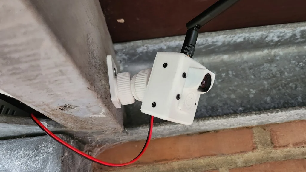
About this 3D model
ESP32-CAM AI-Thinker CASING NEW VERSION: https://makerworld.com/en/models/246973 & https://makerworld.com/en/models/246514 Ball joint / Ball screw / Ball base Credit: DieZopfe - https://www.thingiverse.com/thing:4739696 ESP32Cam-Case2vents+usb+mb-space.stl (Case with space for esp32-cam-mb, usb plug and tiny air gap at the top) ESP32Cam-Case2vents+topseal.stl (Case without antenna hole, ideal for outdoor) ESP32Cam-Caseantennahole+2vents+topseal.stl (Case with antenna hole, ideal for outdoor) ESP32Cam-Caseantennahole+3vents.stl (Case with antennahole, and 3 vents at bottom and tiny air gap at the top) Before i started work on this case, i wanted it to have the following features: Movable mount, considered gopro style, but ended up with ball joint (which works perfect for my usecase) Changable lens holder (stock 8x8mm lens, aswell as bigger 14x14mm lenses in the future) Easy to print with no supports (my printer sucks) Very little hardware required USB or pin powered, with ability to leave ESP32-CAM-MB attached inside SD-card space Hardware required: 4x m2.5x4 (Lens adaptor) 4x m2.5x5 (Front-casing mount to rear-casing) 2x m2x5 (Rear-casing to ball-joint) 1x m2x6 (Mounting-extension - 6mm screw or longer) Assembly: Check clearances (14x14 lens with screw tabs doesnt fit unless the tabs are removed) Screw lens plate to front casing with 4x m2.5x4 screws Insert ESP32-Cam with camera (and antenna cable if used) - Mind the cable and be gentle. Push antenna screw through top-hole (if used) Screw ball-joint WITH finger-screw in between to the rear casing with 2x M2x5 screws Run cables through rear casing, and connect to esp board (5v top right, GND right below, AI-thinker board) Push rear casing into front casing (Mind then antenna cable - i found that if you push antenna cable through the bottom vent, its easier to manage) Last 4 screws goes in both sides, top and bottom. Et voilà