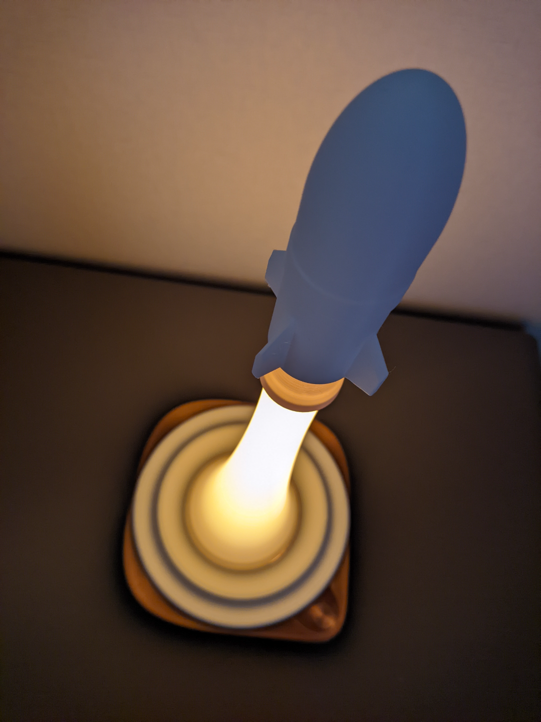
About this 3D model
Note: COB LED strips generate a significant amount of heat, it is advisable to avoid using them unattended. You may consider substituting them with ordinary LED strips or a smaller number of LEDs. CAUTION : COB LEDs produce substantial heat; this light should NEVER be left unattended Creating this lamp requires three LED strips, each approximately 20cm long, a touch-sensitive LED controller (with a 1.5cm diameter touch-sensitive copper foil), some wires, tape, and a soldering iron. To fabricate this model, you will need three 20cm COB LED strips (60cm in total), one LED controller equipped with a touch sensor (1.5cm diameter), some wire, tape, and a soldering iron. First, you need to solder the LED controller and LED strips as shown in the image. This image is for reference only. If your components require different connections, please ensure you take note. First, solder the LED strips in series, then connect them to the LED controller. The second step involves threading the LED strips and cables through the hole in the base, from the outside inwards. The hole is not sufficiently large to accommodate the USB connector, so you must thread them from the outside to the inside. Alternatively, you can opt for the "base for USB" variant, which features a larger opening. However, I have not tested this version. :D If you encounter any issues, please let me know. Secondly, thread the strips and cables through the hole in the base, from the outside inwards. The hole's dimensions are insufficient to accommodate the USB connector, so you must thread them from the outside to the inside. Alternatively, you can opt for the "base for USB" model, which boasts a larger opening. I have not tested this version, so if you encounter any difficulties, please inform me. :D Assemble the touch button as shown in the image (adhesive may be required). Assemble the touch button (adhesive may be necessary). Secure the LED strip to the supports. Ideally, the supports should be printed with ABS or another heat-resistant material. Attach the LED strip to the supports. LEDs generate considerable heat, so if feasible, print the supports with ABS . Snap on the base's cover plate (the small component in the bottom left corner of the image). The base is designed with a designated area for cable management. The cable management solution in this version is not optimal, but the model uploaded has been improved. Attach the cover plate for the base, ensuring a more refined aesthetic (the smaller component in the bottom left corner of the photograph). The base features a designated area for cable management. The cable management system in this version is not optimal, but the uploaded model has been enhanced. Finally, assemble the "smoke" and rocket. Finally, assemble the smoke and the rocket. It is highly recommended to utilize an LED controller capable of adjusting brightness. Otherwise, the supports might quickly deform under high brightness levels. I strongly advise using a controller that enables brightness adjustment to prolong the lamp's lifespan and maintain a lower temperature.