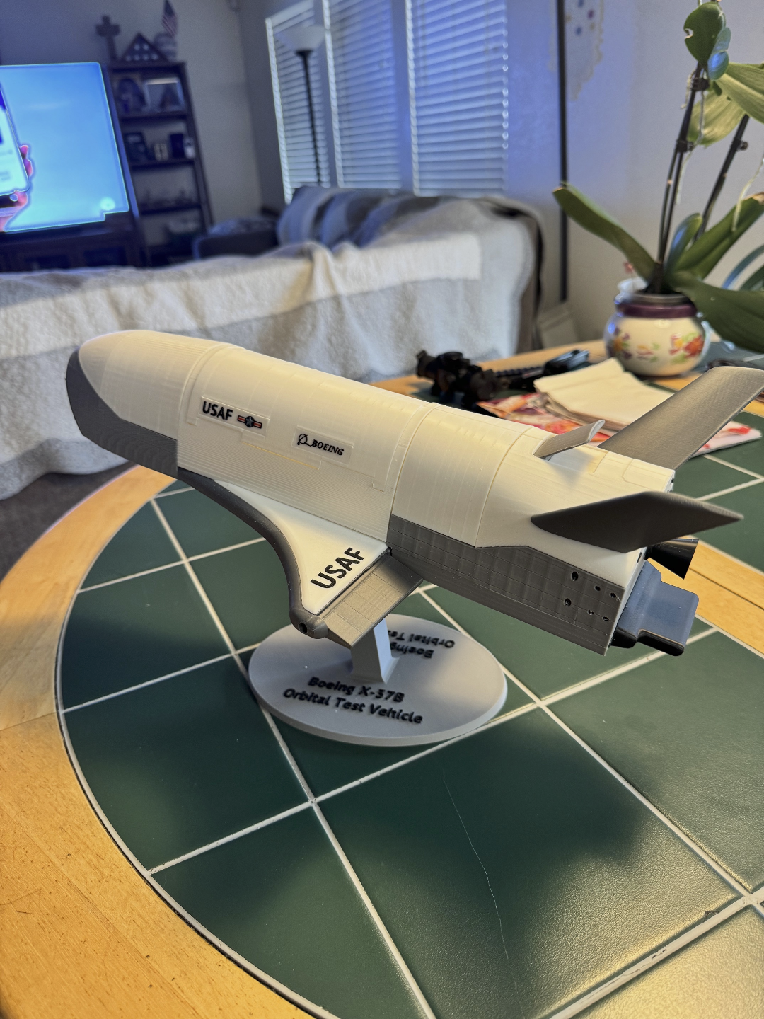
About this 3D model
11/14/2024: For those of you who are interested in the scale of this model, I did not have a specific scale in mind when designing this but with a 422mm model and based on an 8.8m X-37, this results in a 4.8% scale model. (1:21) This model is about 42.2cm (16.6 inches) long. Is has opening payload bay doors, moveable flaps and speed brake. I couldn't think of anything to put in the PL bay, so it is empty. I took inspiration from Martin Taichl (https://www.printables.com/@Martin) and attempted to make this model as a kit with no glue required. I also designed the parts to reduce, if not eliminate, the need to paint - the main reason I purchased the Bambu X1-C. First, let me say I printed this with a Bambu X1-C printer using PLA as the main filament with PETG as the interface between the part and support. If you have multi-filament capability, then I highly suggest using the PLA and PETG in this manner. For all pieces I used a 0.4 mm nozzle, but I had issues with printing the Boeing and Air Force logos (specifically the very small red stripe). I split the model into four sections: the wing, payload bay, the aft section, and the forward section. Now, to discuss how I put the model together assuming you print and put together the parts in this order. Starting with the wing section. Print the wings (wing left and wing right), the flaps (left and right), the pins for the flaps (one short, one longer – 2 for each wing half), and the spacer for the pins (2). So, first printing the wing section . I suggest you use dark filament (I used “space grey”) for the wing halves to simulate the thermal protection system (TPS) material on the X-37B. I save printing in black for the nose tip, nozzle, and the connectors on the back surface – but more on that later. My slicer (Bambu Studio) suggested I print the wing horizontal but that resulted in some rough areas inside the cavity for the flap. While you cannot see this area when assembled, I decided to print it vertical, and the print was much cleaner. I will note however that printing a single wing (with supports) in the vertical orientation took 6 ½ hours and horizontally it took 2 ½ hours. Next, I printed the flaps. As suggested by the slicer I printed these vertically. The two holes in each flap are different depths. I would suggest orienting the flap, so the short hole (narrower outboard end) is at the bottom even though this makes the narrower outboard edge on the print plate and the wider edge up. I suggest at least a 5mm brim. I had no issues but if this still fails, then I suggest reorienting, so the wider edge is on the print plate (still use brim). The outboard edge being on the print plate makes it easier to remove the support filament inside the hole. Then print the pins and the spacers. For the pins and spacers, again, I suggest printing with at least 5mm of brim around the bottom to help with adhesion during the print. I also suggest that when printing all the ‘bags’ for connecting left/right halves you use at least a 5mm brim. Assembly of wings: After removing all support material, just insert the flap, with short hole side outboard, into the wing cavity, and insert the pins. This should result in a movable wing, about +/- 15 degrees. I designed the fit to be tight but just in case I added the spacer to insert against the inside pin. When installed the spacer should be smooth or slightly inside the wing inside edge. This prevents the pin working its way out and you having to disassemble to correct. If you ever want to disassemble the wings and flaps, then I suggest not installing the short outboard pins. It is very hard to remove once installed. The flap will work sufficiently without the outboard pin because of the tight tolerances. Same procedure for second wing half. Next, print the wing top. With this I suggest white filament for the part and black filament for the lettering. You print the wing top horizontally which lets you change the filament to black for the raised ‘USAF’ lettering if you do not have multi-filament capability. The wing top will secure the two wing halves together. Next is the mid-body, or payload (PL) bay section . All this, I suggest you print this in white filament. You print the PL bottom sections horizontally, and the PL doors and the pivot rods vertically. The four pivot rods may need brim at bottom to support adhesion. After removing support filament, the assembly is straight forward. I suggest being very careful removing support from inside the rod holes in both the bottoms and the doors, so as not to break sides of the bottom section. Before final installation of the pivot rods into the PL doors, if you want to test the movement of the PL doors then instead of inserting the pivot rod (difficult, but not impossible, to remove once installed) use a length of the 1.75mm filament as temporary rods. This is a looser fit, but this allows the verification of the doors' rotational movement. Once each half is assembled then adding the tw