About this 3D model
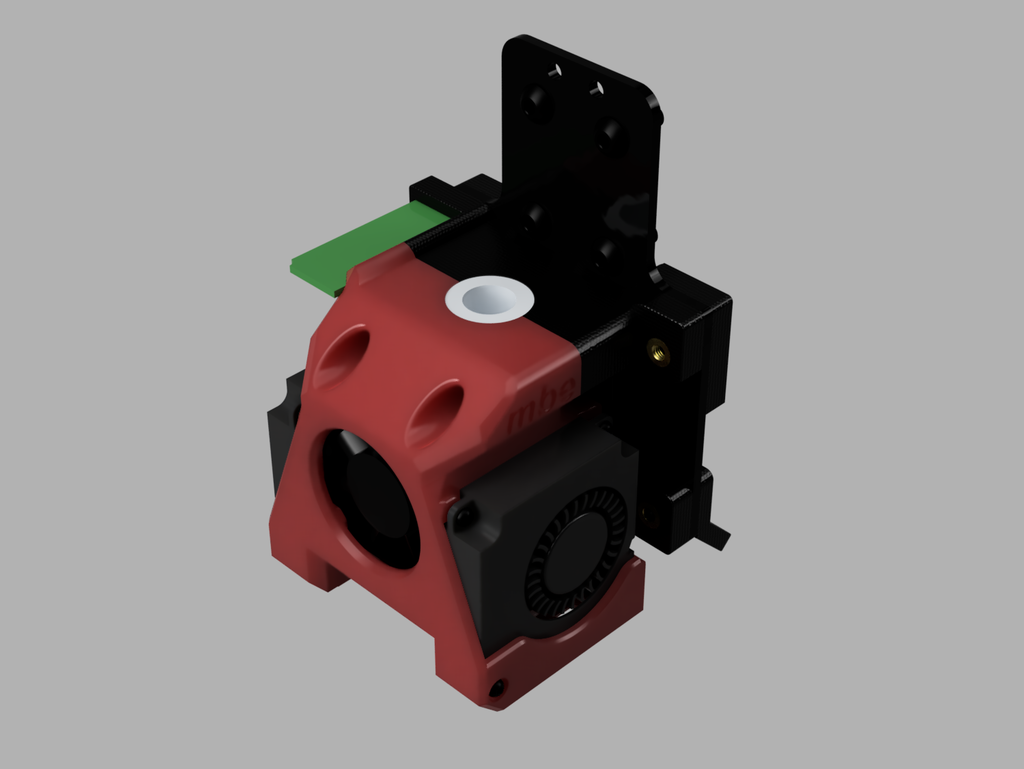
Summary This is the first and the most important upgrade for your Anycubic i3 Mega S as it dramatically improves cooling and thus PLA print quality. It mounts on the X carriage mounting plate, so no disassembly of X axis is necessary. This is important, as re-assembling the X axis rods for trouble free operation requires precision, tools, and knowledge. It re-uses the standard head PCB, so the connections are simple and elegant. As a bonus, you get an adjustable X axis belt tensioner, part lighting LEDs and all of this in a lighter package than your stock metal assembly. A magnetic bed probe will be posted soon as a separate thing, but will require a firmware upgrade and will only fit ABS prints due to available elasticity of ABS for press-fitting magnets. The head is designed to be easily exchangeable (to one with a different nozzle size, for an example). For this you only need to undo the stock head connector and unscrew two mounting screws. The alternative head requires its own fans and a PCB, though, so you can opt for switching the hot-end instead. The fan shroud visual was inspired by the great work of what has now become Apogee head on Orbiter Projects page, but was designed from ground up for easier printing on an open printer and for extra future features required. My other designs: mbe Filament Spool Holder TODO: Add more pictures of printhead and assembly process Print Settings Printer Brand: Anycubic Printer: i3 Mega S/Pro Rafts: Doesn't Matter Supports: Yes Resolution: 0.16 Infill: 10% Filament: Anycubic ABS, PLA Red, Black Notes: Fan shroud and the attachment plate must be printed in ABS for any sort of durability. PLA will work for some time, though if you only print PLA and do not install 5x5 magnets for the probe. You can certainly print PLA first to check if you like the design as it is an easy, high quality print for stock Anycubic i3 Mega S at some 50mm/s for the base speed and 6mm retraction distance. I did not have good results for structure, nor quality with PETG and the design is optimised for ABS printing on an open printer with a draft shield. I used a thick layer of hair spray on ultrabase, which is easy to clean up later with isopropyl alcohol. Glue stick will work with similar results, so it is more of a personal preference. Belt tensioner must be printed in PLA for stiffness and LED bracket is much easier to print in PLA because of the overhang. All parts will print without supports, but you can improve some details with supports. Support settings will differ from slicer to slicer, so use whatever has worked for you in the past. If you are printing ABS on stock Anycubic i3 Mega S, the gcode file for the Fan Shroud should do the trick for you. The rest of the parts are a walk in the park compared to this one and should cause no problems with your regular settings. Remember to re-level your bed for ABS, as 100C will sag it much more than 60C. For better results, until you upgrade to mesh leveling, you can level closer to the area, where your actual print will be instead of leveling for far out corners. Post-Printing Vitamins required You will need all new fans: 2 x 4010 radial and 1 x 3010 or 3015 axial, rated at 12V. Pick ball bearing fans of the best quality you are ready to pay for. Airflow matters - the more the better, aim at >2.9CFM. You will need seven threaded inserts - M3 x 4mm. The largest outside diameter of mine is about 5.3 mm, so you need to find similar to work with the hole size in the design. You will need four M3 x 8 mm ISO4762 bolts and three M3 x 25 mm ISO4762 bolts to assemble the head to the carriage. You will need four M2 x 6 mm ISO4762 bolts and two M2 x 12 mm ISO4762 bolts to mount part cooling fans. As for the hot-end fan, most will keep themselves in place by friction alone, but you can secure 3010 fan with M2.5 x 12 mm screws and 3015 with M2.5 x 16 mm if you are careful and keep in mind you have only 1 mm of thread to catch. Alternatively, use a drop of hot glue. You will need two JST PH 2.0 90deg sockets and two plugs for a very neat connection, but other ways and methods will work, of course. You can use the type of 12V LED strip you have at hand. Connections The LED strip connects to the right hand side connector (hot-end fan) and the extra part cooling fan to the left side connector (original part cooling fan). The probe will connect to the three pin connector that is not populated on a stock machine. X axis limit switch X axis limit switch will have to be moved inwards on the original post and will now be held in place with a single M3 bolt. That bolt is more than enough to keep it in place, but a custom post for the switch could be designed at will. In a future release of a combined attachment plate for the printhead and a remote direct dual drive extruder, this is addressed by an adjustable limit switch actuator arm. How I Designed This We run an engineering lab that uses various additive manufacturing technologies. Among others, we have about