About this 3D model
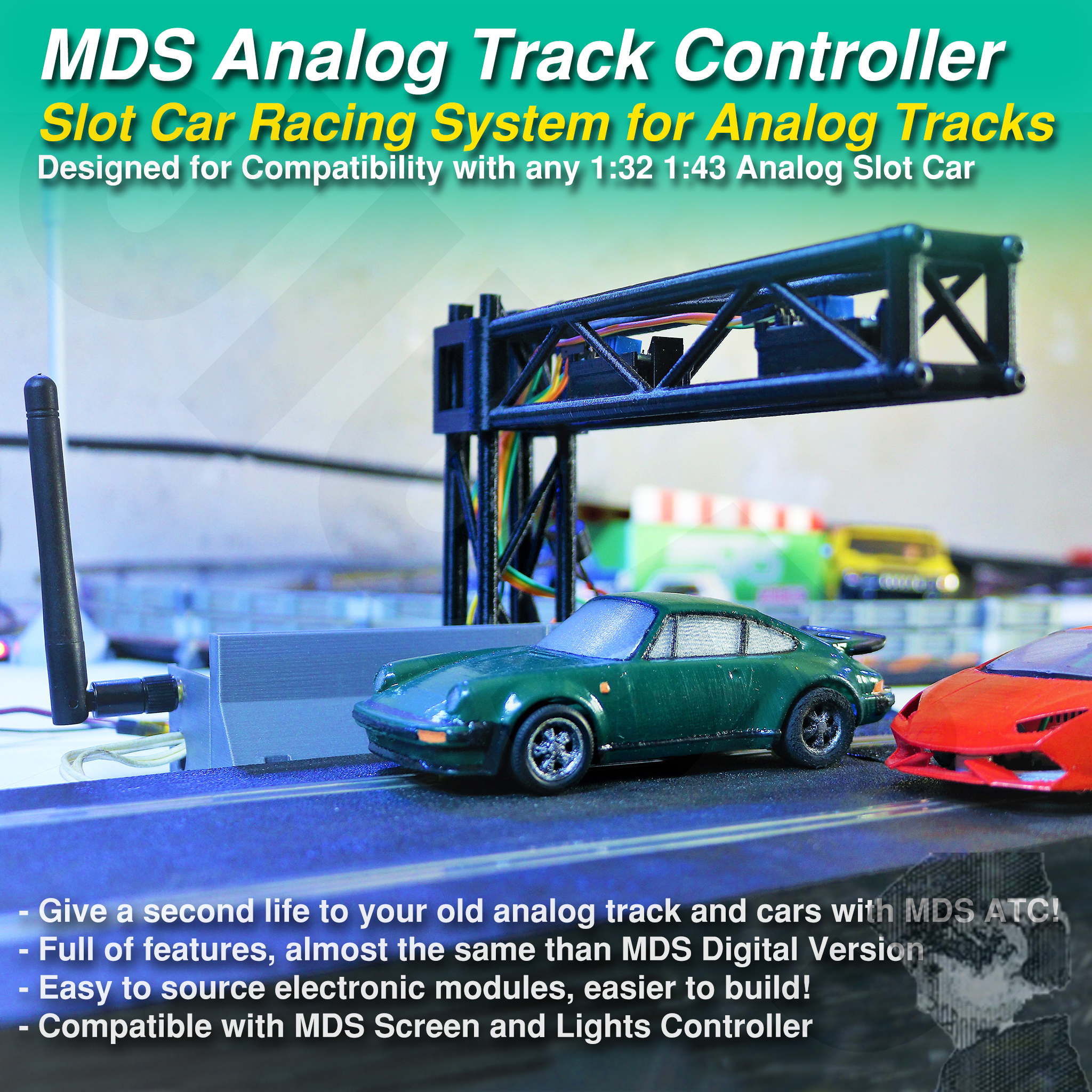
My Store is Closed. Design not on sale here. Do not buy if you are allowed. MyDigitalSlot Analog Track Controller Maybe the name of this product is a little confusing… is it Digital or Analog? I hope you soon find it has the best of both worlds! It is a Digital way of controlling your Analog Slot Cars. After developing all MyDigitalSlot System I realized that most of the people want to use their old track but more important, their analog car collection they made during years or decades… So having to print new cars and track parts for their “new digital hobby” didn’t make sense at all… That is why I started struggling about how to satisfy those hobbyists with MDS technology. So I started thinking about how to use any track or cars with MyDigitalSlot… And that is how the ATC (Analog Track Controller) born. THE CODE I use to make it work IS NOT PART OF THE PRODUCT. Please, read more at the end of the publication in “The Code” Chapter to know more about how to get the code Main Characteristics Wireless and Rechargeable Controllers Lap Counting and Race System up to 4 players Race Configuration and Invitation System Fuel Consumption and Boxes Stop and Go for Race starts Start Lights in Controllers and Track Lights Start and Celebration Sounds in Track Controller Compatible with MDS Track Lighting and Info Screen Dual Pit Lane and Deviations compatible (in development) This time, as I’m trying to reach every slot Hobbyist, I have tried to simplify as much as possible the design of the “Analog Track Controller”, and have made an extra effort to offer a compact version but also an “Easy to Build” version, which uses “Electronic Modules” instead of “Electronic Components”. This is the difference between having to build this with a lot of component soldering or just mostly using Dupont cables to connect the electronic modules. I tried to accomplish this as much as possible for the Radio Controllers, but for this new “Analog Track Controller” you will need a soldering iron just for one or two points. How the whole system works I made this project after discovering how good Arduino + RF modules worked in my “RC Surface Radio” project. As you probably know, MDS System (the Digital one) is also based in Arduino + RF for both the controllers and the cars. In this Analog version of the thing, the Arduino + RF remain in the Radio Controller, but instead of inside the cars, the receiver is in the “Analog Track Controller”. Now the way you electrify your lanes is with Mosfet Modules from the Analog Track Controller, being able to control 2 lanes simultaneously with one ATC. Infra-Red cheap modules over the track are responsible of detecting Laps but also Boxes when you stop under it. A simple 5V buzzer can add some sounds to your races, with starting and winning sounds. The communication between Radios and Analog Track Controller is bi-directional, that is how all the magic (coding) works, but also between radios and other devices like the “Track Lighting and Info Screen” one. Building the system As a good starting point, you will need two MDS Controllers and the ATC (Analog Track Controller). Printing the STLs for these parts is quite easy, compared with sourcing all the needed electronics and components for the system. If you want to source parts for the Radio Controllers and build them you will have to take a deep look to the “MDS Controller” publication. For the ATC please go on reading. You can build the “Compact” ATC or the “Easy” one, being this last one the one I recommend to begin. The Easy Analog Track Controller Sourced Parts Needed for “Easy” ATC Arduino NANO or similar one NRF24L01+ PA Module + Adaptor Arduino Nano Expansion Board Red 2x Mosfet Modules 2x TCRT5000 “blue” Infrared Modules DC-DC 5V3A Step-Down Regulator Female-Female Dupont Cables, 150 or 200mm long ones 2.54mm female sockets or cut Dupont female 2.54mm male sockets or cut Dupont male 12-15V ACDC approx. 2A Adapter with standard connector or your slot one If you want to make it even easier, you can use an Arduino Nano-RF which includes the NRF24L01 module and will avoid connecting 7 cables between the Arduino and the RF antenna. It is also the one you need for the compact version. The DC-DC module is mandatory if you don’t want to burn your Arduino. Why not powering the Arduino naturally by the Vin Pin, as the Shield is intended to do? Because you will connect 2 IR modules plus 2 Mosfet Modules to the Arduino at 5V, and the 5V are converted from Vin Voltage by the Arduino with a little converter which gets really hot and make the whole system instable. On the other hand, using the little DC-DC module will allow us to do much more over the 5V rail and the Arduino won’t get as hot, but also will allow us to use more than 12V input power, which would be a requirement for some analog cars and tracks. Making the Connections The Nano Shield will help a lot as a breakout board and will allow us to connect most of modules really easy, for example you will