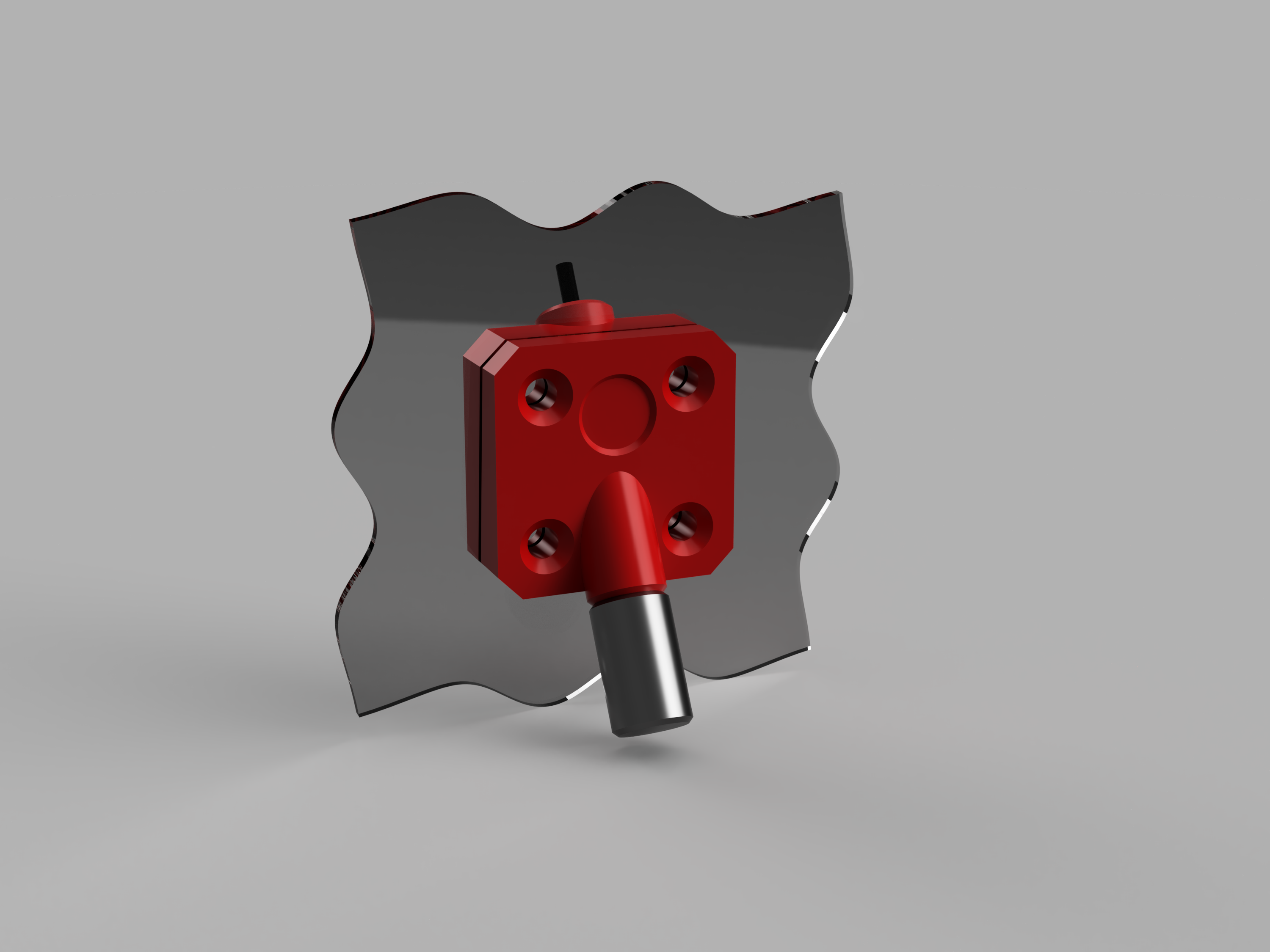
About this 3D model
Materials 4x countersink M3 bolts 4x M3 nuts 4mm teflon tube (optional) 2x 4x2mm magnets (optional) M3 set screw Assembly mark and drill holes for the M3 bolts into the drybox wall insert the M3 nuts into the inner bushing insert one of the magnets into the outer bushing bolt both sides of the bushing to the drybox wall run a 4mm drill bit through the hole for the teflon tube cut a 35mm long piece of teflon tube, insert it into the bushing from outside of the box and keep pushing it in until it's flush on the inside insert the other magnet into the cap; the polarity has to align with the first magnet so that the cap can stick to the recess in the outer bushing run some filament through the tube, push the cap onto the teflon tube, then take it off there should be a short piece of filament sticking out of the teflon tube; if that's not the case, shorten the teflon tube so that you can comfortably pull out the filament again if the teflon tube doesn't sit firmly in the bushing, retain it using the M3 set screw Adjustments This bushing was designed for a box with tapered sides, situated just above the printer. The design takes into account two main angles: one between the wall and the bottom of the box, and the other between the wall of the box and the filament path. Look at the mechanical drawing for reference. You can adjust these angles in the f3d file. The fastest way to approximate what angles you need is to take a picture of your box from the side in its final position, preferably along with the filament running from the spool to the printer. You can then import this picture into the Fusion 360 design to make the appropriate changes. Don't forget to adjust the thickness of the wall as well, otherwise the screw holes will be misaligned.