About this 3D model
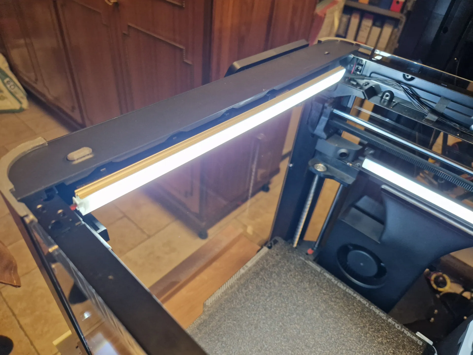
ENGLISH (Segue versione in ITALIANO ) This project allows for mounting (via magnetic attachment) a 5v LED strip to illuminate the interior of the Bambulab P1P (and newer P1S) by utilizing the available USB port behind the screen. This minimizes cable clutter and also enables the use of the hole available on the upper side of the front shell of the printer to insert a manual button switch (this LED is independent from stock light and its switch is manual only, no software). BOM: n. 1 - 5V adhesive LED strip, preferably with included USB cable ( https://amzn.to/3C2wpyn ) n. 1 - Aluminum LED profile (readily available at hardware stores - https://amzn.to/3C47Hhi ) n. 1 - Switch ( https://amzn.to/3qhcPMa ) n. 12 - 8x1 mm magnets ( https://amzn.to/3C3tYLT ) n. 1 - M4x10 screw (optional) n. 1 - M3x10 screw (optional) n. 1 - Pair of 2-pin JST connectors (optional - https://amzn.to/43bVoLv) TOOLS: Electrical wire Soldering iron and solder Heat shrink tubing Glue (such as Loctite Attak) Aluminum saw Scissors ASSEMBLY: Print the attached files as shown in the figure (attached is the .3mf file). Preferably in PETG or ABS/ASA . 2. Use pliers to remove the highlighted part of the main piece ( Base.stl ) to allow cable passage later. 3. Solder the positive (+) and negative (-) terminals (usually red and black respectively) with the switch and the LED strip as shown in the following diagram. For convenience (i.e., easy removal of the LED strip), you can connect the LED strip and its power cables using a 2-pin connector (such as a JST connector). Before proceeding, ensure proper functionality by connecting everything to a PC's USB port or a cellphone charger. 4. Place the button as shown in the following figure and then position the button cap ( Button.stl ). 5. Glue the magnets together to obtain 4 pairs and, after applying glue to the circular slots on USB guide.stl and Base guide.stl, place each pair in its respective slot. Press firmly to ensure proper insertion. 6. Join Base.stl and Base guide.stl using the dovetail joint. It is better to apply glue to ensure proper adhesion. 7. Unscrew the indicated screw located on the back of the upper shell of the printer and lift the plastic shell, being careful not to break the interlocking tabs. 8. Position the assembled pieces using the button as a reference. Then close the printer shell and, inserting an Allen wrench into the groove of Base.stl , reinsert the previously removed screw. 9. Insert the USB connector into USB guide.stl as shown in the figure. Pay attention to the orientation: with the USB inserted, the flange should be at the bottom. 10. Cut the LED strip to the desired length (approximately 30 cm) as instructed by the product. Cut the aluminum bar accordingly. Glue the freshly cut LED strip to it and close it with the appropriate semi-transparent cover. 11. Place 4 magnets corresponding to the already placed pairs and apply glue to the exposed side. Then place the aluminum strip on the flanges and hold it against the magnets until the glue dries (a few minutes). Then, by pulling away the strip, the magnets should remain attached to it. 12. For increased vibration resistance, it would be better to insert an M4x10 screw underneath Base.stl through the printer frame. 13. OPTIONAL - For enhanced illumination at the print bed level, you can print Lower LED (optional).stl and insert a small LED strip (also 5V) connected in parallel with the main one. The connection cables can pass through as seen in the previous image (between the frame and belt support, there is a small passage channel). The printed piece fits into the frame but for better stability, it is advisable to secure it to the frame using an M3x10 screw in the designated hole. NOTE: This additional LED may cause glare in the webcam. At the end, the illumination of the print area is significantly improved. The button, located on the upper part of the shell, allows for easy manual operation. ________________________________________________________________________________________________________________ ITALIANO Questo progetto permette di montare (tramite attacco magnetico) una barretta LED per illuminare l'interno della Bambulab P1P (e la più recente P1S) sfruttando la porta USB disponibile dietro lo schermo. Ciò riduce al minimo il passaggio di cavi e, inoltre, consente di sfruttare il foro presente sul lato superiore della scocca frontale della stampante per inserire un agevole interruttore manuale (non controllabile via software). BOM: n. 1 - Striscia led adesiva 5v, possibilmente con cavo USB incluso ( https://amzn.to/3C2wpyn ) n. 1 - Profilato in alluminio per LED (facilmente acquistabili presso ferramenta - https://amzn.to/3C47Hhi https://amzn.to/3C47Hhi ) n. 1 - Interruttore (https://amzn.to/3qhcPMa https://amzn.to/3qhcPMa ) n. 12 - Magneti 8x1 mm (https://amzn.to/3C3tYLT https://amzn.to/3C3tYLT ) n. 1 - Vite M4x10 (opzionale) n. 1 - Vite M3x10 (opzionale) n. 1 - Coppia connettore JST 2 pin (opzionale -