About this 3D model
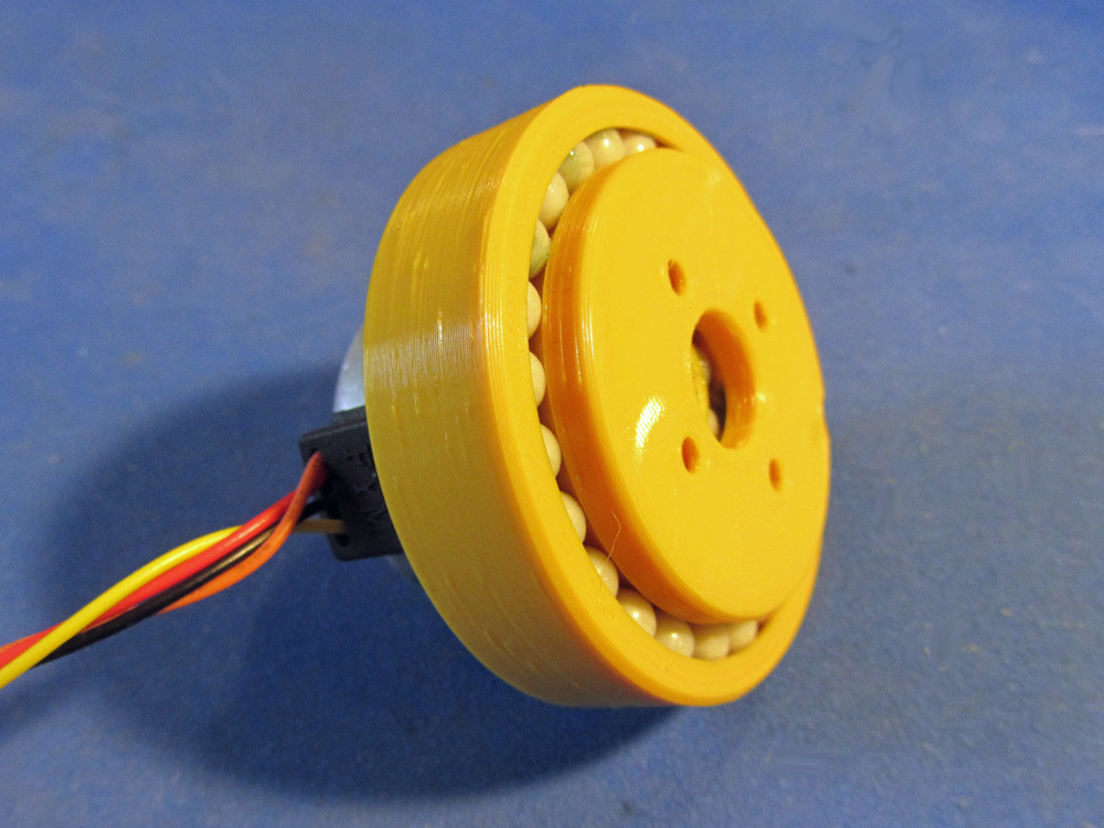
This compound cycloidal drive is designed for 35mm "tin can"-style stepper motors. It has two stages, yielding a 49:1 drive reduction. The flat package and integral slew bearing (using 6mm dia. Airsoft BB's) on the output plate make it great for robotic applications. This gear reducer is very similar to my compound planetary robot actuator ( https://www.thingiverse.com/thing:3293562 ). This cycloidal version is simpler and easier to print, but the high-speed eccentric motion of the cam does introduce some vibration and it doesn't seem to be quite as efficient as the planetary version.. Watch it go: https://youtu.be/HxCDbEL9afc Print Settings Printer: UDIO Rafts: No Supports: No Resolution: 0.2mm Infill: 20% Filament: Inland PLA Dandelion Yellow Notes: The parts all print up pretty easily. I've included 2 different hubs - one for motors with a 2mm dia. shaft and one for a 3mm dia shaft. After printing go over all beaing race surfaces and cam surfaces with a scraper or sandpaper to eliminate any blobs or ridges. Post-Printing Assembly To assemble, you will need: 1 6-32 set screw 4 4-40 nuts 2 4-40 x 0.25" screws 1 35mm stepper motor (eg: Moon's 35PM048S8-08001) 32 airsoft BB's Before assembling, read over all the directions. Also, I'd suggest dry assembling the bearings first to make sure they run smoothly before doing the complete final assembly. Press the four 4-40 nuts into the hex pockets on the underside of the the output plate (pins7.STL). If they do not hold snugly, use a drop of superglue. Tap the funky diagonal set-screw hole in the hub with a 6-32 tap (refer to the 7th photo above). Start the set screw in the diagonal hole. Position the hub inside compound cam as shown in the 5th photo with the ball insertion cutouts aligned. Insert 8 BB's in the top race and 8 more into the bottom race. Add a little light grease or vaseline to the bearing balls. Screw the motor to the base with the two 4-40 screws. Align the compound cam with the base exactly as shown in the 6th photo, and slide onto the motor shaft. Tighten down the setscrew. It just jams into the motor shaft diagonally, but should hold tight enough for this small motor. Apply some grease to the cams. Insert the output plate (pins7.STL) over the cam so that the ball cutout aligns with the cutout on the base. Insert 24 BB's and apply some grease to the balls. Category: Engineering