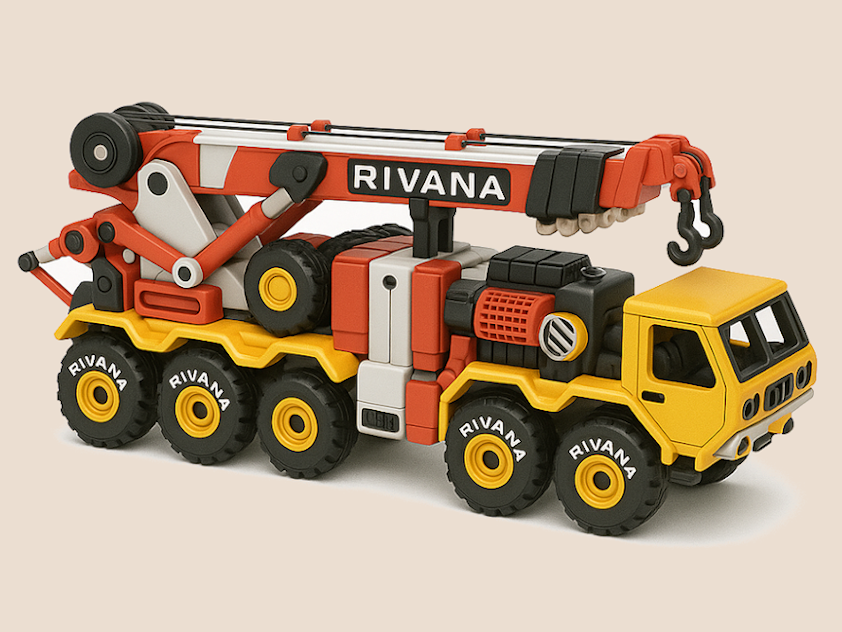
About this 3D model
The Multi-Mission Recovery System (MMRS) is a powerful vehicle designed to retrieve and repair disabled military vehicles in challenging environments. It boasts a 360-degree rotating boom with a 41-foot reach and impressive lifting capacity, handling even heavy armored vehicles. Its all-wheel drive and advanced suspension tackle tough terrain, while operator safety is prioritized with armored protection and remote controls. I am very thankful to Mr Benoît Lussier for his feedbacks which has helped me refine the model further. There are three ways to print this. As single piece:- Please download STL file but there wont be any movements. Multiple Pieces :- Download 3mf file with Full_dismantled.3mf.BEST QUALITY OUTPUT. Please use the 3mf file for assembly also. CHECK EASE OF PRINTING TITLE BELOW Combined:- You may use any 3D viewer software like 3D builder in windows to merge components according to your printer and filaments. The sky is the limit for this. You may find a sample file ending with combined.3mf. EASE OF PRINTING Print the wheel axles at minimum 60% infill Density The 14th and 15th Plates can be printed with filament change for the brand names on the top, if you choose so. It is recommended to print Plate 16 with PETG. ASSEMBLY OF MODEL This is done in 7 steps. Please follow the steps. 1)_ASSEMBLY OF UNDERCARRIAGE Attention:- There are three sizes of bolts used in undercarriage assembly. The bolt(2 in number) used for the tilt arm of the 2nd axle is the smallest ones. The bolts(2 in number) used at the ends of the front to rear axle counter link is the longest while rest are medium bolts. Ensure nominal movements( not too tight and not too loose) between the links for perfect working. You can either use a piece of filament or metal locking pins through the holes in the bolt to lock the links or you can glue to heads of the bolts to its counterpart. Gluing will work for all the joints except at the inter axle links. There you may have to you a metal lock pin or filament. 2)_ASSEMBLY OF TURRET 3)_ASSEMBLY OF REAR PLATFORM 4)_ASSEMBLY OF MIDDLE ELEVATOR 5)_ASSEMBLY OF FRONT PLATFORM 6)_ASSEMBLY OF CABIN 7)_MATING OF PARTS STATIC DISPLAY LOCKING The are specific mechanisms provided by which various links can be locked in different poses. Please use a small piece of filament to lock the links as shown in the instructions below Movements Included 1) ELEVATOR MOVEMENTS 2)SYNCHRONIZING GEARS 3)TURRET MOVEMENTS 4)FRONT DUAL WITH REAR COUNTER STEERING NOTE The tolerances to some elements are zero which has been intentionally provided to friction lock the elements while not in movements. You may have to fine tune the tolerance from your end using scaling function in slicer to ensure good fit without compromising movements. This also applies for the pins that make rotation possible between elements. Please proceed with printing all the pins after testing printing a pin and testing the fit of a joint. You should be able to find the adequate scaling factor with this. Supports should be provided as required. Appreciate the makes uploads. Open for suggestions.