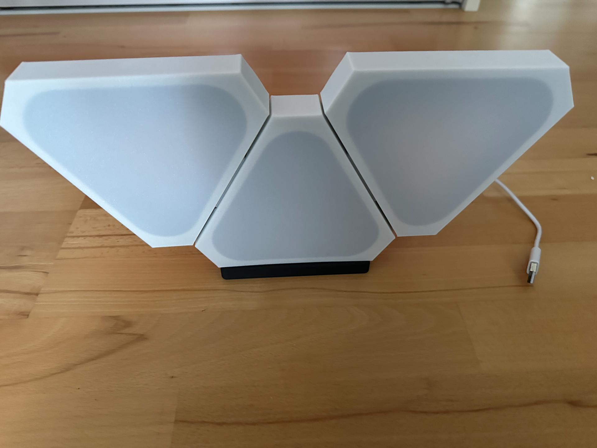
About this 3D model
Some RGB Leds, good area gets lighted, a Stand and possibility to exapand in future. Remembered I printed a Nanoleaf replica before, but had some things I wanted to change, so only few remained from Original: https://www.printables.com/de/model/46814-nano-leaf-replica-remake-to-get-better-diffusion So whats new: Use of Wemos D1 Mini ESP8622 or Wemos D1 ESP 32 should be possible, for larger Installations option for usage of a round plugged power source. No extra electronics Box, 2 different option Baseplate for each esp type Holes for M3 + M4 screws Diffusors optimzied for less material and better “clickability” Stand with USB cable routing to back and integrated M4 screws, if you want to expand could work by adding other Stands and multiples of 2 Segments. Base parts back closed, so few light shines to back when standing, but also original with cut out and other diffusors As i had no long enough screws by hand also a set of spacers, nuts, and 14xM4 screws to print -> if you have use real 12-14mm M3/M4 Printing is far easy: Take provided 3MFs 1) Base parts - just take out the electronics base you do not need. Add a cable tunnel per segment you want to connect - so hides connections and helps stability with printed screws If you print the Back Diffursor you may want to scale it down to 99% for easier fit -has to be glued anyway Otherwise no special print settings - standard Layer height and gyroid 10% 2) Base and Screws, here choose fewest layer heigt possibe to get them good, go gyroid 10% infill There are no big parts prints fast enough to do it for better quality If you have 6-14mm M3 screws, there is also a more stable version with integrated M3 nut instead one sticking out. Electronics As we use an ESP go for Software you like. I choosed WLED for ease o use and Home Assistant integration, go fastled or whatever you want 4 led per edge soldering example: To minimize soldering I suggest to prepare as following. In Case you have a bunch of 3pin Fan male/female adapters to could use them between segments. First Cut Led Stripe into 4 each Led segments, you need 3 of them for each panel, so for example 3 panel lamp: 9*4x Led segments Then you have to solder them together, i would prepare each panel its own. ! Please look after directory arrows on the stripe ! Starting for "Main with eletronics" made some pictures on the way to it. ESP 4cm cable Segment 8cm cable Segment 6,5cm cable Segment 6,5cm cable Segment 8cm cable Segment 6,5cm cable Segment 8cm cable Segment 6,5cm cable Segment 6,5cm cable Segment Check if lenghts are good before next step! Also a good time to recheck if every led is ok ;) Now it is time to put them through Cable channel, until reaching last panel, take your time there is few space to push stripes between the panels. Check again if everthing is working. Now put the panels gently into their final position, and attaching the spacers. After that put segments roughly to their end position and then beginning to fasten Led Stripe from ESP I applied a dip of hot glue to secure it and afterwards every segment to hold everything in place. If you printed the Main parts with holes you might want to glue back diffusers in too. Diffusors on side panels can be closed now, depending on using the Stand and USB Cable vs dedicated power adapter secure this parts. Important: some ESP have a status Led which could case some wrong colours, just take care you do something against this, i used a smal tip of dark duct tape As last step it is time to gently put on diffusor for electronics part. Have fun.