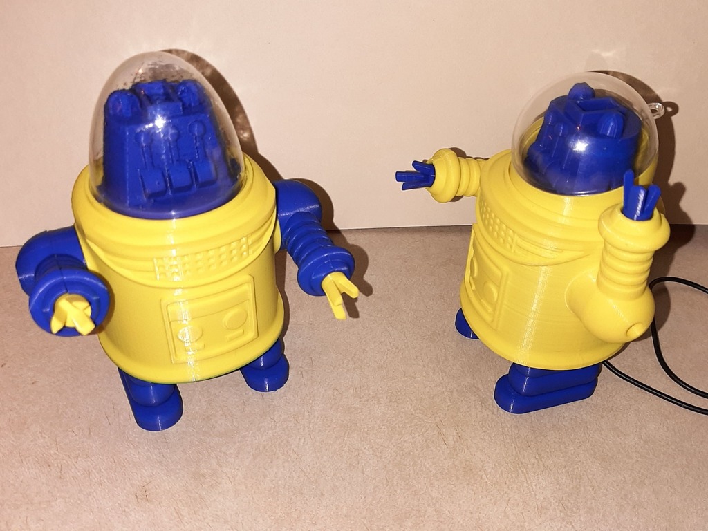
About this 3D model
Summary Youtube video: https://youtu.be/-c5GyUUYcsI This 3d printed project is another remote controlled pin walking toy robot that is driven by a single motor. It can move forward or spin in place. It uses a two way to one way rotation mechanism to accomplish this. It has 2 control options. You can control it with 2 SPDT switches or use the IR control board I designed.The motor is an N20 gear motor. The wired remote version used a 6V 160 RPM motor. The IR controlled version used a 6V 200 RPM motor.The battery for the wired remote version is a 4 AA battery pack. The IR controlled version uses a single cell lipo. The remote control is a universal infrared remote unit set up to transmit 12 bit Sony codes. The ir commands are interpreted by a microcontroller and drive the motor through a L9110s motor driver. For this project the right angle headers for connecting the IR sensor to the board are not use. The IR sensor is connected to the board with a length of 3 conductor wire solderd directly to the board. This is due to limited space. There are 2 options for the dome. I will include a mold for making a vacuum forming buck of the dome. I know nothing about vacuum forming but was able to make a plaster of paris buck with the mold. Then I used a simple vacuum forming box and shop vac to mold the plastic. A heat gun was used to heat the plastic. There are Youtube videos showing how to make a vacuum former. The other option is a 50mm clear ornamant globe you can buy on Ebay. There are two versions of the mcu board. One uses an Attiny85 and the other uses a Picaxe 08M2. I used to do a lot with the Picaxe and it's a nice fit for this project. It's Basic language is less intimidating than the Arduino C++ language. It also contains built in commands for reading Sony ir codes. I will include links to the EasyEda schematics and boards for both versions. You can order the boards through JCLPCB, PCBWay, or any place you choose. I got 5 of each board from JCLPCB for a under 20 dollars. You just have to watch which shipping method you pick. The only surface mount component on the boards is the L9110s but it's it can be easily hand soldered. The resistors are all 1/8 Watt. The gerber files for having the boards manufactured will be on the Github for either the Picaxe ar Attiny board.You will need to zip them up to send them to the pcb manufacturer. You can also open the project in EasyEda and get the zip files from there. You will need some special hardware for the build. The 52 mm brass shafts is cut from 1/8 inch rod but 3MM should work. I used 1/8 inch brass welding rod from a Tractor Supply. The screws are 3MMX12MM button socket head cap machine screws and 2MMX8MM self tapping screws. I got them off Ebay. Some thin double sided tape for mounting the battery. Some foam double sided tape for mounting the control board. Super glue. An 1/8 inch drill. O rings for springs to make the arms poseable. I got the O rings in an O ring kit from Harbor Freight. You may need a JST 2.0 PH 2 male connectors to connect the battery to the controller board if your lipo has a different connector. Some Dupont connecters for connecting the motor to the control board. The most difficult part of the assembly is the cams, gear, pawl, axle mechanism. I will try to descibe it but you should watch the video if you want to build it. The 52 MM 1/8 inch brass rod is mounted permanently to the right cam. I pressed it on with a drill press for exact alignment but I've also made one by tapping it in with a hammer. Just be careful to get it straight. The right_bevel gear_30T and right_gear spacer are mounted permanently to each other by tapping them together with a hammer using the 3D printed arbor. The left_gear_spacer_cam and left_bevel gear_30T are also joined permanently using the hammer and arbor. They are keyed so the cam location will be aligned to the ratchet on the gear. You may have to do some adjusting with files and sandpaper if the parts are too tight to fit together. If they are too loose for the press fit you can use super glue. You can also try adjusting slicer settings to get a better fit. After you get the right bevel gear and left bevel gear assemblies complete you need to drill them out with an 1/8 inch drill so that the brass axle spins freely inside them. I used a cordless drill. Make sure you get the drill started straight. You could also use a drill press. The left_pawl and right_pawl will probably need to be drilled out for ease of assembly. Try to drill them out just enough to allow them to be slid onto the axle and their positions to be adjusted. The axle will attached to these parts (the pawls) permanently with super glue after they are in their final position. Be careful when holding them to drill. It's easy to break or crack the little fingers on the pawls. The right and left pawls are glued to the 1/8 inch axle and have to oriented properly to the right cam so the pins stay in phase. Slide the right cam and axle through the r