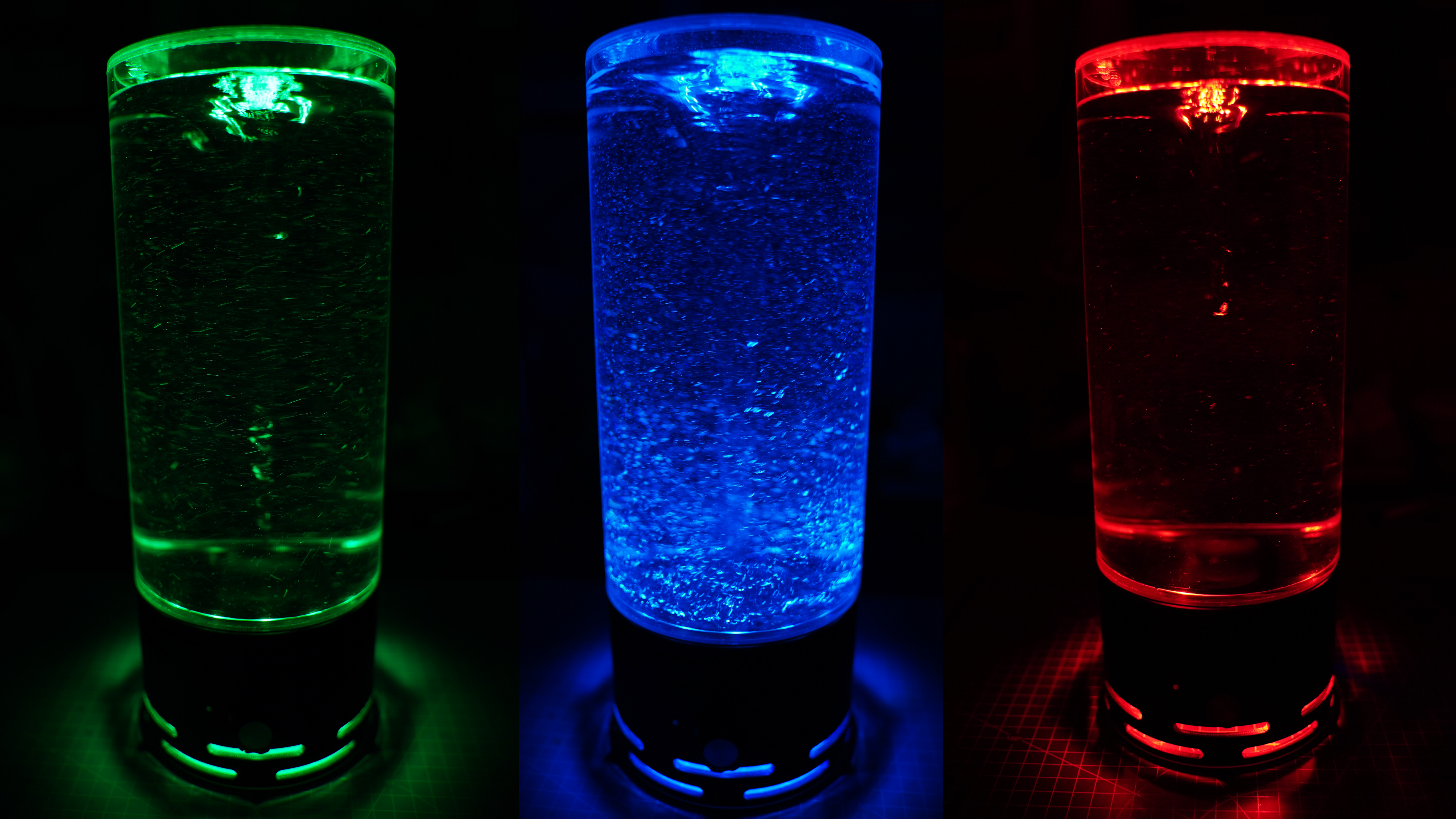
About this 3D model
Boost Me Support me <3 Hello 3D-friends :) I designed a simple vortex machine here. You can adjust the whirlpool strength with the controller. The lighting can be controlled individually. This can be controlled via push button, remote control or smartphone app. And believe me, it looks even better in real life than on the photos. The light effect that shines on the ceiling also looks absolutely great. Material List: (Affiliate Links) Switch Countersunk screws 2,5mm, 8mm length DC-Jack 5,5x2,5 Power Supply 12V 3A RGB LED RINGS (Playstation 5) Glitter Magnetic Stirrer Poti 10K Ohm Acrifix Plexiglass Glue (Acrylic): https://amzn.to/3IEYu3u 2x DC-DC Step Down Module: https://amzn.to/3W0lQDq PLA to Plexiglass Glue (Ruderer L530): https://amzn.to/3Iz5LBP PLA Filamentum WIZARD’S VOODOO: https://amzn.to/3ZmQBp8 or PLA Burnt Titanium Filament Transparent Glow in the Dark or: Filament Transparent Clear Plexiglass Tube (Acrylic): https://www.ebay.de/itm/374036770365?var=642980141537 2x Plexiglass Tube Cap (Acrylic): https://www.ebay.de/itm/204156430773?var=504738303851 PC FAN Corsair: https://amzn.to/3vPYJAP Connection Cable 0.6mm2 (22 AWG) 3mm PMMA Glassfiber: https://amzn.to/3VZ5MSz Voltmeter Display Push Button Set (6x6x10mm) 2x Neodym Magnet 20mm x 3mm Destilled Clear Water You can assemble the Plexiglass tank yourself: This requires a tube with an outer diameter of 133mm and an inner diameter of 127mm and 2 matching end caps. I chose a tube length of 250mm, but longer should be possible. First, one side of the tube is glued to a cap. This is only possible with the Glue Acrifix. The best thing to do is watch a youtube tutorial !!! The tank can then be filled to about 95%. I used distilled water for this. I also added a pinch of glitter to it. Use the large stirrer (35x9mm) and put it in the tank. Before the lid is glued on, the strudel should be tested first. No liquid should touch the lid at maximum vortex strength. First the stand can be printed. The best way to do this is to use this file in Prusa Slicer: “Wirbelmacher-Stand-FINAL-preconfigured.3mf” All print settings are already optimally configured there. Important: The main color is printed first. Then you switch to a transparent filament. Then again the main color. The next stop is also a filament change, but only serves to insert one of the LED rings. The LED rings must first be desoldered from the microcontroller. The ring should be fixed directly with hot glue. Also consider the correct orientation of the ring because of the cable. This should be at the very back. The cable must also be attached to the floor with adhesive tape so that it does not come into contact with the extruder. Once the print is complete, the tape can be easily removed. Now continue the print with the main color. Then switch back to transparent filament and finally I printed on TPU to have a rubber foot. If you also want to do this, it is important to reduce the speed manually on the printer to about 50%. The temperature should be increased to 235c. Preparing the fan: In my case it is a Corsair PWM fan with a diameter of 140mm. I still had this one. Of course, any PC fan with 120mm or 140mm can be used. But then you probably have to draw a cap for the fan motor with the magnets yourself. I also included the Fusion 360 file and the STEP file for this. Only 2 of the 4 wires are required here. 12v & GND (click me for PINOUT) First remove the rotor cap by pulling straight up. It may be that you need some strength. A pipe wrench may help. All rotor blades are then broken off and the rest removed with a cutter or saw. Now "Vortexmacher-Rotor-FINAL-preconfigured.3mf" can be printed. Then the 2 magnets can be inserted and fixed with a bit of hot glue. Important: Keep in mind the correct poles of the magnets for the stirrer. So test this first before you press the magnets in! Then the rotor cap can be assembled with the magnet cap. If it doesn't fit, just sand something down. Then fix it with some glue. The fan frame can now also be removed. Simply saw off the connecting rods to the frame at the outer end. Now the modified fan can be glued into the stand with hot glue. It is important that it is perfectly centered: Now you can solder the electronics together. This is the circuit diagram: Here are a few pictures for the electronic part: Remove the plastic cover from the USB microcontroller. Now solder 2 wires on for 5v & Ground. Desolder the push button and resolder 2 wires on the left side as shown in the picture. They can then be soldered back to the extra push button. The connection to the LED rings must also be removed first, as one of the rings must already be inserted during the print itself. If you are new to soldering and having trouble with it, use soldering fluid. Solder 3 wires to the large potentiometer. Note the correct wiring here. The potentiometer must be unsoldered on one of the DC-DC Step Down Modules. The connection to the large potentiometer is then soldered to the 3 conta