About this 3D model
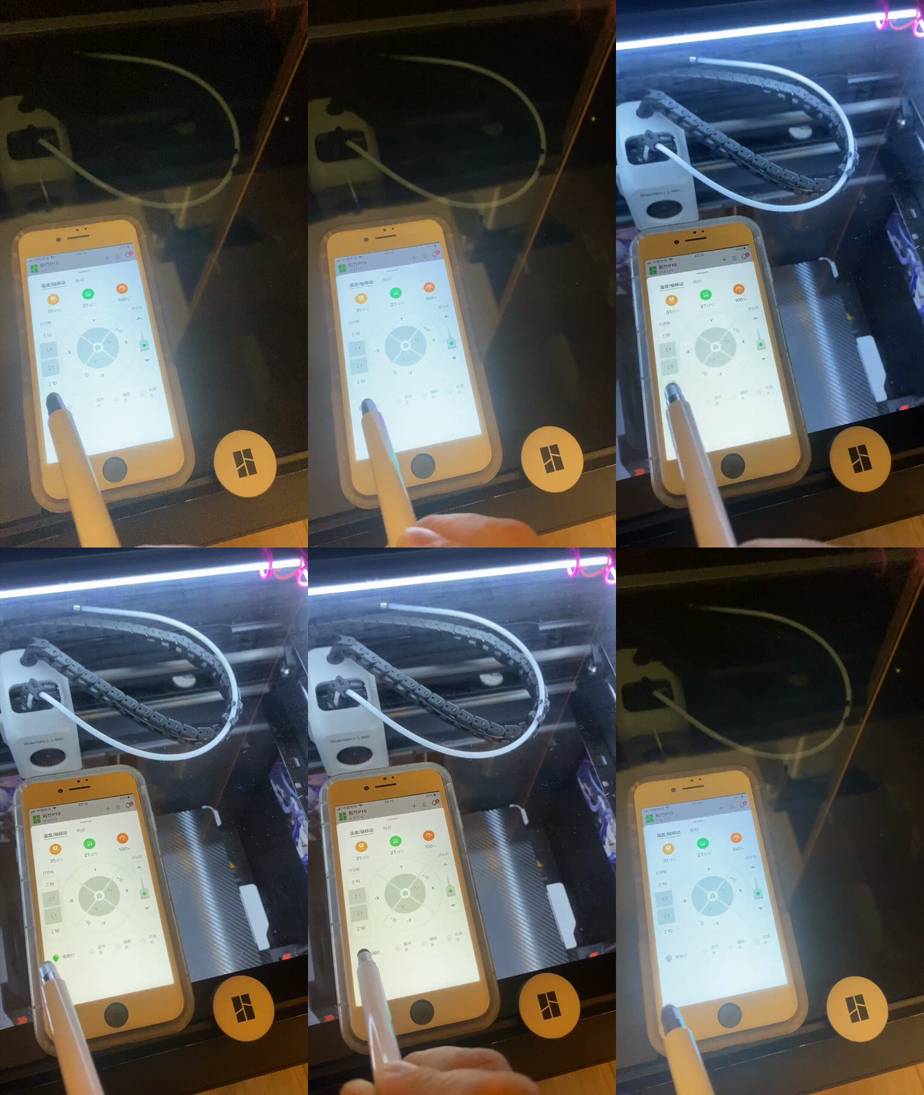
First of all Thank you for sharing this model, it is exactly what I needed ( •̀ ω •́ )y~~~~ Since my machine is in a corner, LED lights are a must-have, so I added a few M3 heat-shrink nuts holes to the model, which are convenient for installing LED lights. The electrical control idea is from B station user YungWai, I added a dual-control design on this basis. This allows the LED light to be controlled by the Bambu Handy on your phone/PC, as well as a conventional switch. (It can be turned on individually, but to turn it off, both sides must be turned off simultaneously). Hardware List Diagram Description Quantity M3*5 Hex Socket Flat Head Screws 12 pieces M3*3*4.2 Heat-Shrink Nuts 16 pieces PG1313 LED Triangle Corner Line Light Groove 1 meter Flat Head with White Light, 3-6V, Self-locking switch, Diameter 16mm 1 piece 5v led strip 1 meter 1-Way Relay 1 piece GH1.25 Wire 2Pin 1 piece N/A Dupont Wire/JST Connector Several Installation 1. Embed the heat-shrink nuts into the bracket using a soldering iron. (Friends who have already printed the original model can drill a 4mm diameter hole and then embed the heat-shrink nuts, no need to re-print, the hole location is marked in the figure below). There are two purposes for designing the heat-shrink nuts here: First, it increases the durability of the model and prevents the entire part from being reprinted due to damage to one of the light groove brackets. Second, it increases the design diversity, allowing for different styles of light groove brackets to be designed under the same hole size. The effect after installation is as follows Hole Position Parameters 2. Install the light groove bracket. The bracket I designed here is a universal type, but I found that the purchased light groove is a bit wide and will block a small part of the air outlet. (I plan to design another set of light grooves and brackets later when I have time, and welcome everyone to design light grooves and brackets using the above dimensions). The following shows the installed state (I used a prominent color to print the LED-related parts for easy observation) 3. Cut the light groove, cut the purchased 1-meter aluminum groove into three sections of 28cm, 28cm, and 32cm using a hacksaw. (Cut the LED light strip to the same length, but make sure to cut it at the cut point). PS: Those without tools or who lack confidence in their DIY abilities can ask a hardware store for help. Online stores do not help with cutting, at least not the one I bought from.? After cutting, be sure to use a steel file to polish the surface, be careful, don't cut yourself. Remember to fix the two ends of the LED with double-sided tape. Next, complete the circuit part, refer to the diagram below for wiring (choose one): 1. The light on the switch is always on 2. The light on the switch only lights up when the switch is pressed After wiring, it should look something like this ( The jumper wire on the relay is connected incorrectly here, it should be connected to the low-level trigger side ) Install the light on the riser: Install the light strip first, then the riser. The finished product is as follows: * 1) Although the front LED light has a hole for it, it is recommended to use the USB strip light shared by bri0nac https://makerworld.com/zh/models/71763#profileId-75928 (There are a lot of wires and modules that need to be stored in the front, the strip light is a must-have). Unplug the original light power supply and connect the negative pole (black wire) to the relay (IN) interface. The rest of the wires are hidden in the groove in front of the machine and fixed and covered with black vinegar cloth tape or electrician's tape, which will make it more aesthetically pleasing. So far, that's all~~~~~!