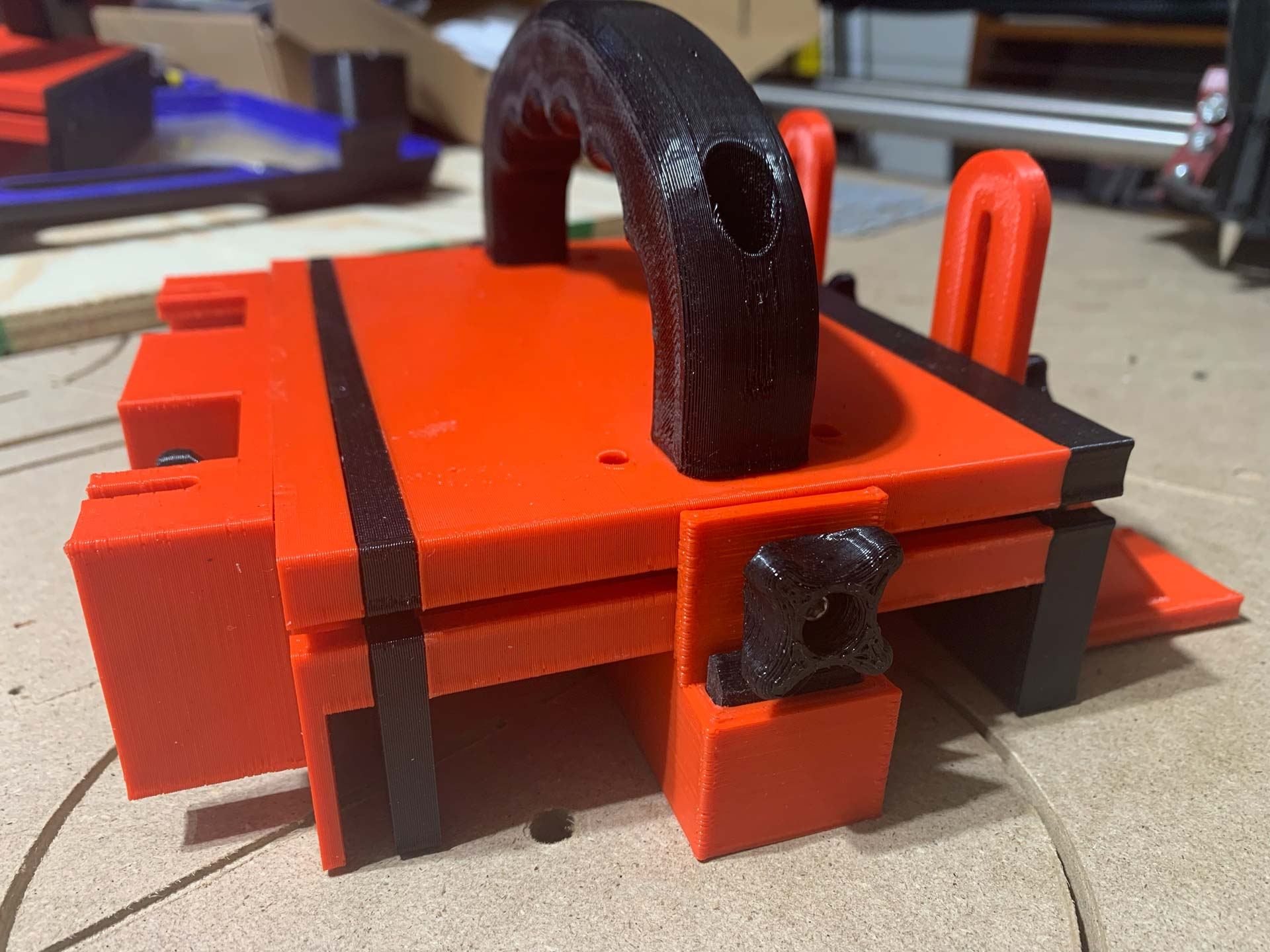
About this 3D model
I've worked on two editions of remix of the excellent push block design by Trobinou (January 23, 2017). One of my remixes does not make use of threaded inserts, while the other (this one) does. (I have not yet posted the non-threaded-insert version of my remix yet. If I get it posted, I'll revise this and link to it here.) BOM and Assembly The following “bill of materials” is from the original listing that I remixed to improve: BOM: Optional: tap (Ø4 mm) to fix the sides — (note: I did not use a tap on mine, if I remember correctly) Two (2) screws, M5×30/35 mm, for the handle Two (2) nuts, M5, for the handle Eight (8) screws, M4×16 mm, for the sides — (note: the original listing spec'd a stainless steel screw with a flange , aka “ TBHC BASE PLATE A2 ”) but I did not buy or use any such special hardware. I just used a regular M4×16 mm screw without any special flange.) Six (6) hexagonal head bolts/screws, M4×20mm, for the knobs (original listing spec'd this one ) Six (6) nuts, M4, for the knobs Your choice of a non-skid coating attached to the lower part for grip — OPTIONS: Rubber pieces cut from a bicycle tire inner tube (I used this). Sand paper (some have reported they used this). Non Slip Self Adhesive Silicone Cuttable Furniture Pads - affiliate link: https://amzn.to/44iU9O9 (credit to @jakeymon for this). Flywoo battery grip — presumably this – (credit to maker @ronsone for this). The original listing spec'd a “rubber plate 290 x 210 mm” but the link it gave is now broken. Here's an affiliate link to the set of threaded inserts that I use: https://amzn.to/3PUAA3F Here's an affiliate link to the set of threaded inserts like those in the video below: https://amzn.to/3EF7Cpb Assembly: At the time when I first created this listing, there was no need of adding assembly steps because the original listing (the one I remixed for improvement) once had a YouTube video showing assembly steps. However, a certain company (that makes a certain product) later demanded that the video be taken down, and YouTube complied. Since then, several fellow makers have explained that simply by considering photos of the final assembled model, you can sort out the details for how to assemble this. Credit to @jakeymon for this excellent video giving great tips about heat inserts: Why threaded inserts in some spots? On the first push block that I made (Trobinou's original design), the heat-set nuts were in deep wells and thus sometimes hard to get straight, causing the screw to approach them wrong and cross thread, and as a result I had some of the printed plastic wells get chewed out and unable to keep ahold to the nut. I much prefer this use of threaded inserts instead of nuts, not everywhere, but on the sides, where it really helps. This design uses threaded inserts that are M4x4x6 on the thinner sides, and it can use those, or longer ones, M4x6x6, on the thicker side. (See below for more details on the various thicknesses of sides provided in this remix.) Improvements / changes in this remix: Knobs are redesigned to print without any supports needed ("Knob.stl" and "Knob_Bottom_Back.stl"). The following parts are all modified so that the bottom ("Bottom.stl") can be removed / replaced without removing all those other parts (in case you accidentally slice into the Bottom enough times that you need to reprint it): Side.stl (actually all three new thicknesses of sides - see below) Side_Plate.stl Router_Plate_v3.stl (named in the original as Router_Plate_v2.stl) NEW: Three thicknesses of sides are provided: 1/2" (12.7mm), 1/4" (6.35mm), and 1/8" (3.175mm). The 1/4" and 1/2" are likely to usually be on always, and the 1/8" can be installed onto the 1/4", or can replace either the 1/4" or the 1/2". The original version had one 7mm thick side, named "Side.stl." This remix offers "Side A (1/4")(6.35mm).stl," "Side B (1/2")(12.7mm).stl," and "Side C (1/8")(3.175mm).stl." * Notes related to the new sides: Most users won't need a 1/8" thick side, but if you are doing veneers or needing something thin, such as shims or whatever, you can print it and use it. If you don't need it, there's no reason to bother with it. The 1/8" thick side prints without supports by having a 1-layer thin sacrifice layer across the bottom of some of the screw holes. After printing, clear out the screw holes with either a soldering iron, a drill, or a knife. The new router plate (Router_Plate_v3.stl) can be mounted on any of the sides, including the 1/8" side, even if the 1/8" side is already mounted onto, say, the 1/4" side. The 1/8" thick side has a 1/4" thick extra "standoff" along its top edge that allows room between it and the 1/4" side, so that a standard table saw blade can pass between them. The 1/4" thick and 1/2" thick sides mount with the same 4 screw holes as the original design. The 1/8" thick side can mount that way, when mounted by itself, or it can use three new screw holes (upper corners and center) if mounted onto, say, the 1/4" side. Remix impr